
In this article, we will use the IDE to check a simple operation of FreeRTOS.
Although it is called FreeRTOS, it is slightly different from Amazon FreeRTOS.
It’s called CMSIS RTOS, and it’s an image of FreeRTOS with a skin on.
STMicro calls it FreeRTOS, so I’ll call it the same here.
Here is the development environment at the time of submission.
PC: Windows 10 OS
IDE: STM32CubeIDE Version 1.1.0
Configurator: STM32CubeMX Version5.4.0
Board: STM32Nucleo-F401RE
Let’s try to build it with the following specifications.
Create a task and a semaphore one at a time.
The task waits for the semaphore and blinks the LED when it gets it.
Interrupt the timer in 1 second cycles and release the semaphore.
Now the LED will blink every second.
Now let’s get started.
Create a new project called F401FreeRTOS in the IDE.
As usual, we will use the STM32F401RE board, so select it in the board selector.
Set the language to the default setting of C.
We have already shown how to create a new project a few times, so we won’t go into it here.
If you do not know how to create a project, please refer to this article.
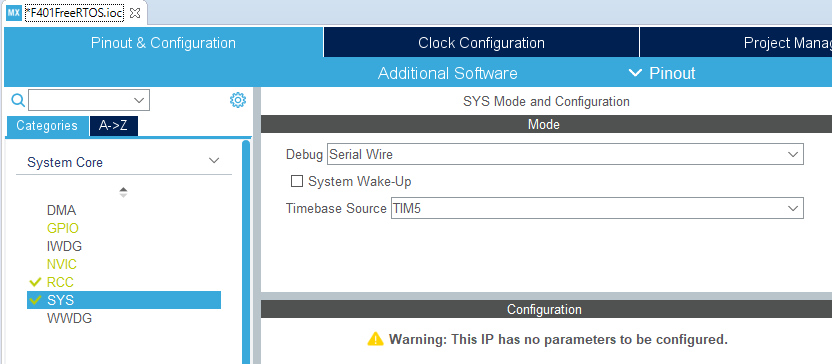
Setting the time base
Select SYS under Categories – System Core in Pinout & Configuration as shown in the image below.
Select TIM5 from Timebase Source.
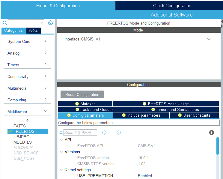
Set up RTOS related settings
.
Select FREERTOS in Categories – Middleware in Pinout & Configuration as shown in the image below.
Then select CMSIS_V1 in Mode – Interface on the right side.
Tasks
If you select the Tasks and Queues tab in Configuration, you will find defaultTask in Tasks, so we will use it as is.
Semaphor
Select Configuration – Timers and Semaphores, click the Add button for Binary Semaphores, and click the OK button when a small window appears.
The semaphore is now automatically named myBinarySem01.
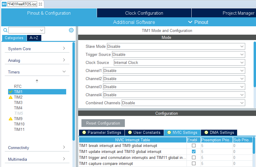
Setting the Interval Timer
We will use TIM1 as the interval timer.
Select TIM1 in Categories – Timers and select Internal Clock from Clock Source in Mode.
Also, check Enable for TIM1 update interrupt and TIM10 global interrupt in Configuraiton – NVIC Settings to allow interrupts.
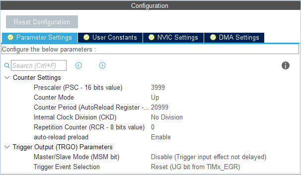
 Parameter Settings
The Parameter Settings should be set as shown in the image below. This will set the value of the interval timer to 1 second.
If you want to check the constants about setting up the timer, please refer to the article here.
Coding
Please write the following code in main.c to run TIM1.
/* USER CODE BEGIN RTOS_QUEUES */
/* add queues, ... */
HAL_TIM_Base_Start_IT(&htim1);
/* USER CODE END RTOS_QUEUES */
HAL_TIM_PeriodElapsedCallback has been added to main.c, so change the code as follows.
void HAL_TIM_PeriodElapsedCallback(TIM_HandleTypeDef *htim)
{
  /* USER CODE BEGIN Callback 0 */

  /* USER CODE END Callback 0 */
  if (htim->Instance == TIM5) {
    HAL_IncTick();
  }
  /* USER CODE BEGIN Callback 1 */
  if (htim == &htim1)
  {
    osSemaphoreRelease(myBinarySem01Handle);
  }
  /* USER CODE END Callback 1 */
}
Also, since StartDefaultTask has been added to main.c, change the code as follows.
void StartDefaultTask(void const * argument)
{
  /* USER CODE BEGIN 5 */
  /* Infinite loop */
  for(;;)
  {
    osSemaphoreWait(myBinarySem01Handle, osWaitForever);
    HAL_GPIO_TogglePin(GPIOA, GPIO_PIN_5);
  }
  /* USER CODE END 5 */
}
The configuration of the tool has changed since I first wrote the document, and the code output by the configurator seems to be quite different.
Try to run it
Let’s try to build and run it.
We have confirmed that the L-tickers work without any problems.
I’ve rushed a bit, but I hope everyone was able to confirm the operation.


