
Once again, we are talking about the STM32CubeIDE. The name is a bit long, so from now on we will simply call STM32CubeIDE as IDE.
In this article we will try to run the Nucleo-F401RE board from STMicro on the IDE. The microcontroller on the board is a 64-pin Cortex-M4 with 96KB of RAM and 512KB of flash memory.
For more information about the board, please refer to here.
I chose a board that is relatively inexpensive and can be purchased online.
Now let’s try to run the board in the IDE. The environment is as follows.
Development environment at the time of posting
PC: Windows 10 OS
IDE: STM32CubeIDE Version1.1.0
Configurator: STM32CubeMX Version5.4.0
Board: STM32Nucleo-F401RE
Try to boot up
Connect the board to the PC with a USB cable.
Start the IDE and select File – New – STM32 Project from the menu.
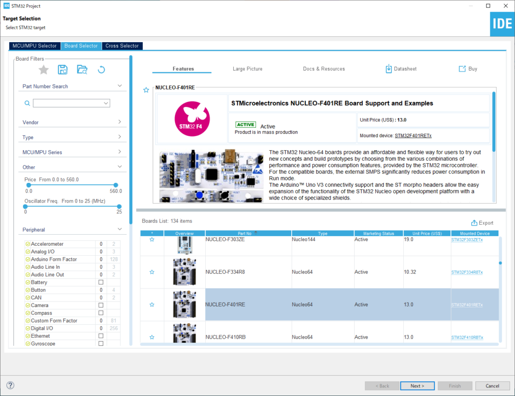
In the Target Selection window, select the Board Selector in the middle tab.
Select NUCLEO-F401RE from the Board List in the right frame and press Next.
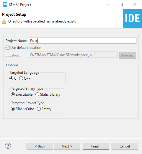
In the Project Setup window, type F401 in the Project Name box and click the Finish button. Enter F401 in the Project Name box, and click the Finish button. (Leave the Options radio button as it is.)
It will ask you “Initialize all peripherals with theri default Mode?
Then press the Yes button.
This kind of project is associated with the STM32CubeMx perspective. Do you want to open this perspective now?
Press the Yes button.
The first thing you need to do is to update the firmware of the device you are using. (In my environment, it took about 7 minutes.)
I hope you will try it when you have enough time.
Try to build it
Select “Project – Build All” to build.
Unless something special happens, you will see the following message in the console and the build will be completed successfully.
xx:xx:xx Build Finished. 0 errors, 0 warnings. (took xxx ms)
If you run the program in this state, you won’t see any behavior.
Try Coding
Now, let’s try to write a program.
On the left side, there is Project Explorer, and the project name is displayed as > F401.
If you click >, you can see the lower level of the project tree.
> F401 > Core > Src to see the main.c file.
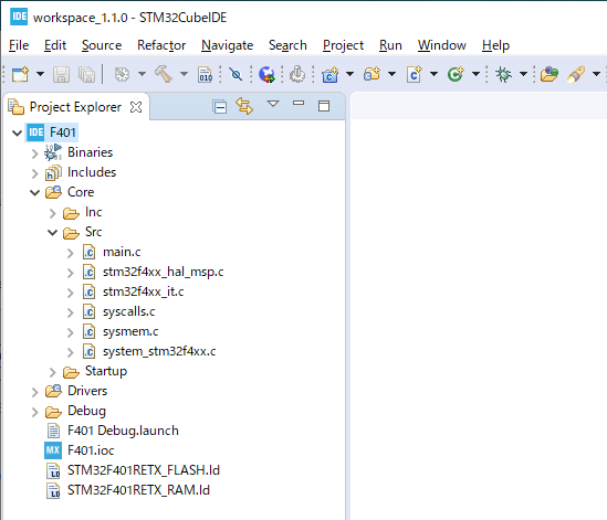
Double-click main.c to edit it in the editor in the center of the screen.
There are some points to note before editing main.c.
The source code is written as follows.
/* Includes ------------------------------------------------------------------*/
#include "main.h"

/* Private includes ----------------------------------------------------------*/
/* USER CODE BEGIN Includes */

/* USER CODE END Includes */
Let’s take the case of including a file as an example.
The code to be added should be written between USER CODE BEGIN xxx and USER CODE END xxx as shown below.
/* USER CODE BEGIN Includes */
#include "hogehoge.h"
/* USER CODE END Includes */
You don’t need to follow this rule if you don’t use the configurator feature, but it is recommended to follow it just in case.
Please note that if you use the configurator, any source code written anywhere other than between “USER CODE BEGIN xxx and USER CODE END xxx” will be deleted.
Conversely, any code written between USER CODE BEGIN and USER CODE END will not be erased by the configurator.
We will talk about the configurator another time.
The first code that is usually written in microcontroller is Japanese “L-tica”.
If you are wondering, “What is “L-tica”?
L stands for “LED” and “tika” stands for “tick-tick”, which means to make the LED tick.
In English, it’s called ”LED blinky”.
This is the most rudimentary form of I/O control and is often used to check the operation of a program.
The circuit diagram of NUCLEO-F401RE can be downloaded from here for your reference.
The LED that can be controlled from the circuit diagram (4/4) is LD2 (green).
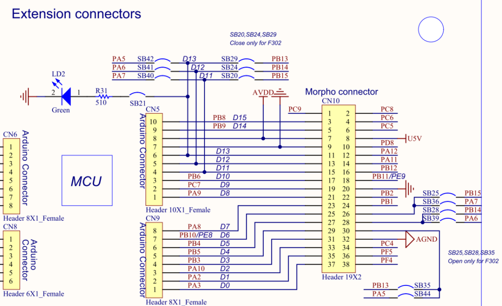
The signal name is D13, but if you look at the schematic (2/4), it is connected to PA5.
PA5 is bit 5 of GPIO port A.
So please write the following code between USER CODE BEGIN 1 and END 1 in main.c.
int main(void)
{
  /* USER CODE BEGIN 1 */ GPIO_InitTypeDef

  GPIO_InitTypeDef GPIO_InitStruct = {0}
  __HAL_RCC_GPIOA_CLK_ENABLE();
  GPIO_InitStruct.Pin = GPIO_PIN_5;
  GPIO_InitStruct.Mode = GPIO_MODE_OUTPUT_PP;
  GPIO_InitStruct.Pull = GPIO_NOPULL;
  GPIO_InitStruct.Speed = GPIO_SPEED_FREQ_LOW;
  HAL_GPIO_Init(GPIOA, &GPIO_InitStruct);

  HAL_GPIO_WritePin(GPIOA, GPIO_PIN_5, GPIO_PIN_SET);
  HAL_GPIO_WritePin(GPIOA, GPIO_PIN_5, GPIO_PIN_RESET);
  HAL_GPIO_TogglePin(GPIOA, GPIO_PIN_5);
  HAL_GPIO_TogglePin(GPIOA, GPIO_PIN_5);

  /* USER CODE END 1 */
Then build it and make sure there are no errors.
Place a breakpoint
Use the keyboard to bring the cursor to the line “HAL_GPIO_WritePin(GPIOA, GPIO_PIN_5, GPIO_PIN_SET);” and press Ctrl+Shift+B.
(Hold down the Ctrl and Shift keys and press the B key.)
Then a ● will appear on the left side of this line. This will mark the breakpoint.
Press Ctrl + Shift + B again to release the breakpoint.
You can also place a breakpoint by double-clicking on the line number with the mouse.
Now select Run – Debug from the menu.
Run the program
After Run – Debug, the program will stop at the line “GPIO_InitTypeDef GPIO_InitStruct = {0};”.
If you select Run – Resume (or press F8), the program will run and stop at the line where you put the breakpoint.
As you probably know, when the program reaches a breakpoint, it will stop there.
From here on, we will execute the program line by line.
The first line to execute is “HAL_GPIO_WritePin(GPIOA, GPIO_PIN_5, GPIO_PIN_SET);”.
GPIO_PIN_SET means to raise the voltage level of this pin to “H”.
This will add voltage to GPIOA (the anode side of the LED), which means that the LED will light up.
Executing the program one line at a time is called “step execution”.
Let’s try stepping through the program.
Select Run – Step Over (or press the F6 key)
The green LED near the center of the board will light up.
The first line to execute is “HAL_GPIO_WritePin(GPIOA, GPIO_PIN_5, GPIO_PIN_RESET);”.
GPIO_PIN_RESET means to reduce the voltage level of this pin to “L”.
This means that the voltage will no longer be supplied to the anode side of the LED, so the LED will turn off.
Now let’s step through the process.
Select Run – Step Over (or press the F6 key)
The LED will turn off.
The next line to execute is “HAL_GPIO_TogglePin(GPIOA, GPIO_PIN_5);”.
Toggle” means to switch between two states.
Since the LED is off now, executing this line will turn on the LED.
Now let’s step through the process.
Select Run – Step Over (or press the F6 key)
The LED will light up.
The next line to execute is also “HAL_GPIO_TogglePin(GPIOA, GPIO_PIN_5);”.
Since the LED is on now, executing this line will turn off the LED.
Now let’s step through the process.
Select Run – Step Over (or press the F6 key)
The LED will turn off.
How did you like it?
In this article, I have introduced a handful of features of the IDE.
In the next article, we will discuss the code we have added.


