
This time, I will use GPIO interrupts.
The following is the development environment at the time of submission.
PC: Windows 10 OS
IDE: STM32CubeIDE Version1.3.0
Configurator: STM32CubeMX Version5.5.0
Board: STM32Nucleo-F401RE
GPIO interrupt overview
Interrupts have a bad image in human society, but they play an important role in microcontroller-based systems.
In terms of content, they are both the same, interrupting what you are doing and processing the interrupt first.
GPIO interrupts are used for input changes.
You can use interrupts when you want to detect a change in the input signal of a port from H to L or from L to H as soon as possible.
For example, suppose you are polling a port for 100msec to check for input signal changes.
If the signal happens to change just after the check is completed, the detection will be delayed because there will be about 100msec until the next check.
If you use a 1msec polling cycle, detection will be faster, but it will also be busier.
This is where the GPIO interrupt comes in.
Using interrupts eliminates the need to sample the state of the input port, and allows us to detect signal changes immediately.
Project Overview
Now let’s try to use the board to actually run the project.
The board has a blue switch, which is connected to the GPIO PC13.
As you can see in the circuit diagram, PC13 is pulled up with a 4.7kΩ resistor.
The other side of the switch is connected to GND, so PC13 is normally at H level and goes to L level when the switch is pressed.
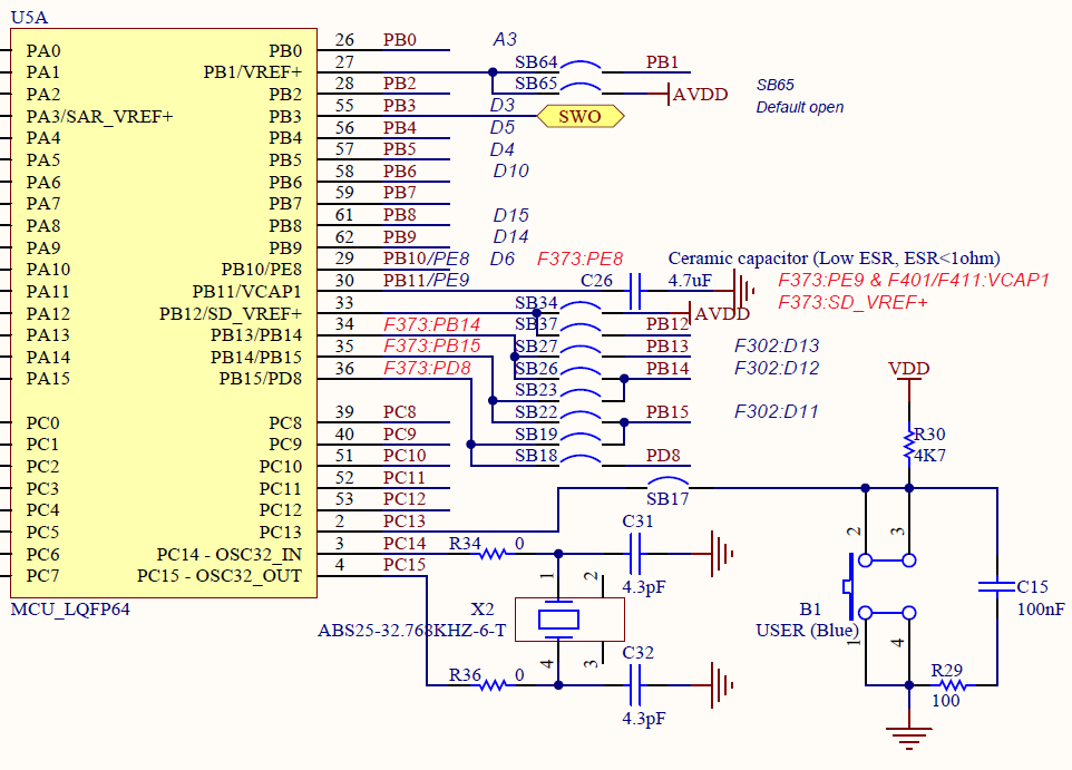
The interrupt will detect when the signal on PC13 changes from “H” to “L”, and we will turn the LED on and off each time.
Since the green LED is connected to PA5, we will try to make it flutter every time the switch is pressed.
Create a project
Start the IDE, select File- New – STM32 Project, when the Target Selection window comes up, select the Board Selector tab, select NUCLEO-F401RE from the Boards List and press Next.
Enter F401GPIoInt as the Project name and press the Finish button.
When it asks “Initialize all peripherals with their default Mode ? Press Yes.
This kind of project is associated with the STM32CubeMx perspective. Do you want to open this perspective now ? Press Yes.
Review and change settings
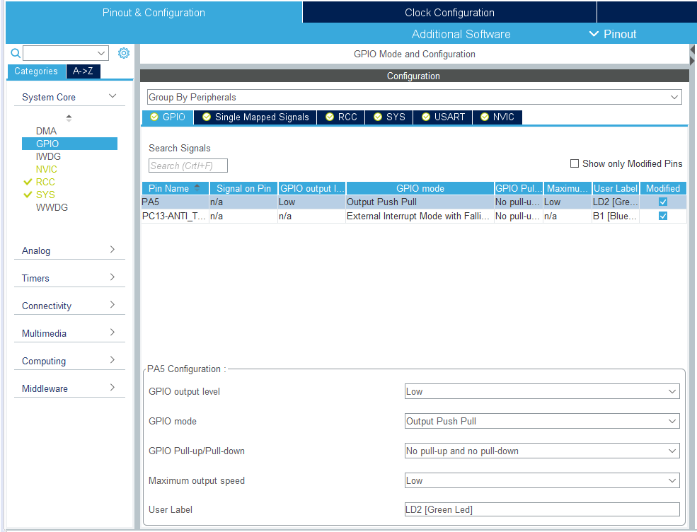
Select GPIO from Pinout & Configuration – Categories – System Core.
With the GPIO tab selected, select PA5 for Pin Name.
Make sure that GPIO mode is set to Output Push Pull.
Next, select the Pin Name PC13-ANTI_TAMP.
Make sure that GPIO mode is set to External Interruput Mode with Falling edge trigger detection.
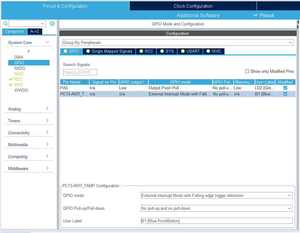
Falling edge is good because it detects the transition from H to L.
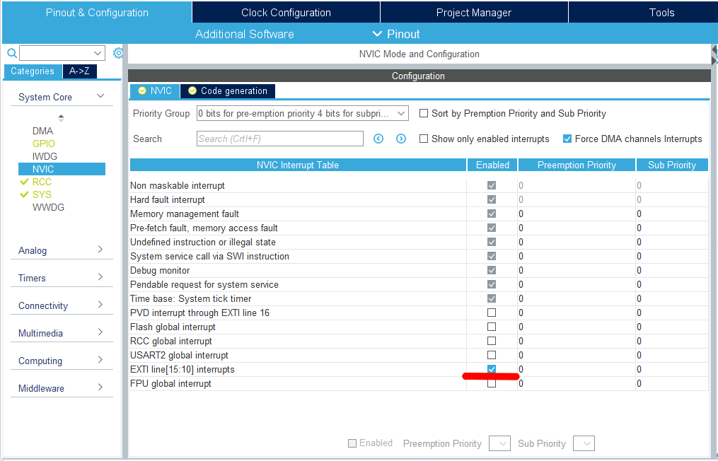
Next, select NVIC from Pinout & Configuration – Categories – System Core.
Then check the Enabled checkbox for EXTI line[15:10] interrupts to allow interrupts.
Coding
This time the interrupt vector is a collection of interrupts for the six lines of EXTI15-10.
Therefore, if you want to detect more than one line, you need to determine which line’s interrupt was received in the interrupt process.
From the Project Explorer, double-click on Core – Src – stm32f4xx_it.c to open it.
At the end of the file, you will find a function called EXTI15_10_IRQHandler().
void EXTI15_10_IRQHandler(void)
{
  /* USER CODE BEGIN EXTI15_10_IRQn 0 */

  /* USER CODE END EXTI15_10_IRQn 0 */
  HAL_GPIO_EXTI_IRQHandler(GPIO_PIN_13);
  /* USER CODE BEGIN EXTI15_10_IRQn 1 */

  /* USER CODE END EXTI15_10_IRQn 1 */
}
In this section, there is a description of HAL_GPIO_EXTI_IRQHandler(GPIO_PIN_13).
Double-click on it to select it, then right-click and select Open Declaration.
There is a description of HAL_GPIO_EXTI_Callback(GPIO_Pin);.
This function is written just below it as follows
__weak void HAL_GPIO_EXTI_Callback(uint16_t GPIO_Pin)
{
  /* Prevent unused argument(s) compilation warning */
  UNUSED(GPIO_Pin);
  /* NOTE: This function Should not be modified, when the callback is needed,
           The HAL_GPIO_EXTI_Callback could be implemented in the user file
   */
}
Since the __weak attribute is attached and “don’t touch this part” is mentioned, I added the following description a little before main().
(If a function with __weak attribute is defined elsewhere, that function will be used preferentially.
/* USER CODE BEGIN 0 */
void HAL_GPIO_EXTI_Callback(uint16_t GPIO_Pin)
{
  if (GPIO_Pin == GPIO_PIN_13)
  {
    HAL_GPIO_TogglePin(GPIOA, GPIO_PIN_5);
  }
}
/* USER CODE END 0 */
Mutterings
Part 1
Oh, then what if you want to detect both PA13 and PC13 lines with interrupts?
When I selected GPIO_EXTI13 for both pins of the microcontroller in the GUI, the later setting became effective, and the GPIO_EXTI13 for the previously set pin went from green to gray.
This means that both PA13 and PC13 (and PB13) cannot be used at the same time.
Part 2
The interrupt functions are processed in the following flow.
void EXTI15_10_IRQHandler(void)
{
  HAL_GPIO_EXTI_IRQHandler(GPIO_PIN_13);
}

void HAL_GPIO_EXTI_IRQHandler(uint16_t GPIO_Pin)
{
  if(__HAL_GPIO_EXTI_GET_IT(GPIO_Pin) ! = RESET)
  {
    __HAL_GPIO_EXTI_CLEAR_IT(GPIO_Pin);
    HAL_GPIO_EXTI_Callback(GPIO_Pin);
  }
}

void HAL_GPIO_EXTI_Callback(uint16_t GPIO_Pin)
{
  if (GPIO_Pin == GPIO_PIN_13)
  {
    HAL_GPIO_TogglePin(GPIOA, GPIO_PIN_5);
  }
}
HAL_GPIO_TogglePin() is a function to invert the output of a GPIO port.
In this state, we don’t need to make a decision, so I set up another one to use PA10 for example as an interrupt, and the configurator output the following code.
void EXTI15_10_IRQHandler(void)
{
  HAL_GPIO_EXTI_IRQHandler(GPIO_PIN_10);
  HAL_GPIO_EXTI_IRQHandler(GPIO_PIN_13);
}
If all six are used for interrupts, then
void EXTI15_10_IRQHandler(void)
{
  HAL_GPIO_EXTI_IRQHandler(GPIO_PIN_10);
  HAL_GPIO_EXTI_IRQHandler(GPIO_PIN_11);
  HAL_GPIO_EXTI_IRQHandler(GPIO_PIN_12);
  HAL_GPIO_EXTI_IRQHandler(GPIO_PIN_13);
  HAL_GPIO_EXTI_IRQHandler(GPIO_PIN_14);
  HAL_GPIO_EXTI_IRQHandler(GPIO_PIN_15);
}
I wonder if it will output a code like this.
Is it only me who feels “Hey ST, please do something about this”?
Execute the program
Now build and run it.
If you get an interrupt every time a switch is pressed and the LED blinks, you have succeeded.


