
In this issue, we will talk about the clock system.
This is a good read for those who are not familiar with clock systems.
The following is a description of the development environment at the time of submission.
PC: Windows 10 OS
IDE: STM32CubeIDE Version1.5.0
Configurator: STM32CubeMX Version6.1.0
Board: STM32Nucleo-F401RE
Create a project
Start the IDE, select File- New – STM32 Project, and when the Target Selection window appears, select the Board Selector tab, select NUCLEO-F401RE from the Boards List, and press the Next button. The following is an example of the use of the
Enter F401Clock as the Project name and press the Finish button.
Enter “Initialize all peripherals with their default Mode ? Press “Yes” when asked “Initialize all peripherals with their default Mode ?
This kind of project is associated with the STM32CubeMx perspective. Do you want to open this perspective now ? Do you want to open this perspective now ?
Check the initial clock settings
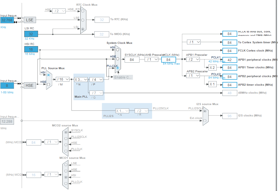
Clock Configuration allows you to view a clock system diagram.
If the diagram is too small to see, create an actual project and check it.
The STM32F401RE has the following four clock sources
LSI : Low Speed Internal
LSE : Low Speed External
HSI : High Speed Internal
HSE : High Speed External
All of these abbreviations are easy to remember.
Internal and External (internal and external transmitters)
Since there is an RC oscillation circuit inside the microcontroller, I think it is often used to reduce cost.
However, this is a little inaccurate, so please use with care.
For example, if you use a microcontroller with USB function, you may need to consider an external oscillator because it requires a certain level of accuracy.
Also, since the oscillation frequency changes with changes in temperature, it may be necessary to consider an external oscillation circuit depending on the environment in which the microcontroller will be used.
In addition, a large frequency error between the serial communication device and the other device may cause a communication error, so it may be necessary to take this into consideration.
The LSI and LSE are used as low-speed 32.768(32)kHz clock sources.
HSI and HSE are used as high-speed clock sources.
In this project, HSE=8MHz. (The square wave input from an external source is 8MHz.)
The microcontroller used on this board (STM32F401RE) has a fixed HSI of 16MHz.
RTC Clock Mux
The RTC Clock Mux is located at the upper left of the system diagram.
Mux is an abbreviation for multiplexer; either HSE/LSE/LSI can be selected, and LSI is selected by default.
Since this board has a 32.768 kHz crystal oscillator implemented (as LSE), it seems that the default should be LSE.
(since LSE should generally be more accurate than LSI)
So let’s change the RTC Clock Mux from LSI to LSE.
Clicking the radio button in the “Trapezoid” of the RTC Clock Mux does not work.
In the System Clock Mux below it, the radio button is light blue and it works when clicked.
The reason for this is that RTC is not enabled.
Check the Activate Clock Source checkbox next to Pinout & Configuration – Categories – Timers – RTC.
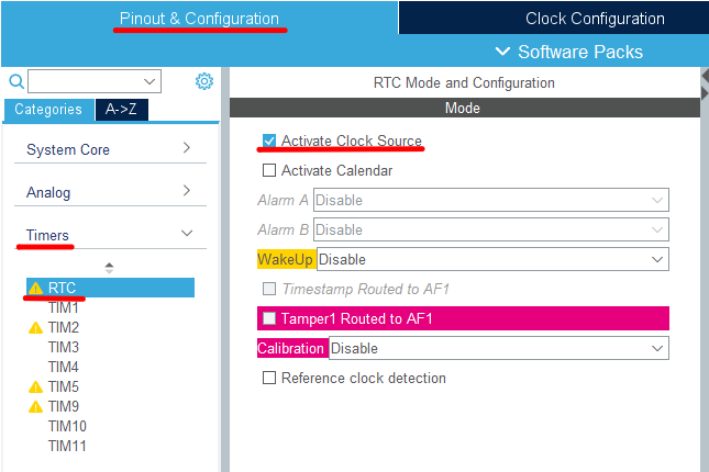
By doing so, the radio button for RTC Clock Mux will be selectable.
Please keep this in mind when using LSE , RTC.
To IWDG Clock
To IWDG(kHz) is written just below RTC Clock Mux.
There is no choice here. The LSI is unconditionally used as the clock source.
IWDG is an independent watchdog timer.
Since we do not need much precision here, it makes no sense to use the LSI.
The fact that it is independent of the main clock system allows runaway detection even if there is a failure in the main clock.
LSE options
If you look at the left side of the RTC Clock Mux, you will see a light blue text box labeled Input frequency, which says 32.768 (kHz).
The light blue color indicates that this part is valid.
Some may think that 32.768 kHz is a halfway figure, but it is not.
2^15 is 32768, and by dividing this frequency, one second can be created exactly.
Therefore, 32.768 kHz is a suitable frequency for RTC.
If you look at the Low Speed Clock(LSE) in Pinout & Configuration – Categories – System Core – RCC, you will see that Crystal/Ceramic Resonator is selected.
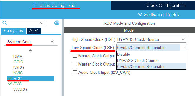
Selecting Disable here will disable the Input frequency text box.
If you do not use an RTC, or if you want to use an LSI as the clock source for the RTC to save on component costs, you can set this to Disable.
If you are using an LSE, you will need to select either Crystal/Ceramic Resonator or BYPASS Clock Source as described earlier.
Select Crystal/Ceramic Resonator if you are using a crystal oscillator, or select BYPASS Clock Source if you are using a square wave input such as a crystal oscillator.
In general, crystal oscillators are more accurate, so you should use that as a guide when selecting which one to use.
If you look at the specifications of crystal units and crystal oscillators, you will find the frequency tolerance (f_tol).
For a crystal oscillator of fair accuracy, this value should be around 5 x 10⁻⁶.
The specifications of the device often include a monthly difference of 00 seconds in the clock function item.
Since this value is a deviation of 1 second, it is sufficient to accumulate it for one month as it is.
60 * 60 * 24 * 31 * 5 / 1000000 = 13.392 seconds
Quartz crystals are available with an accuracy of around 20 x 10-6.
This would result in a deviation of 4 times that amount.
You can decide which component to use based on these figures.
However, the cost must be taken into consideration.
PLL
PLL is an abbreviation for Phase Locked Loop.
You can get an output that is an integral multiple of the input frequency.
This board can produce from 8MHz to 84MHz, allowing the microcomputer to operate at high speed.
PLL Source Mux
You can select the clock source for the PLL from HSI or HSE.
Pinout & Configuration –Category –System Core –HSE cannot be selected if the RCC’s High Speed Clock (HSE) is Disable.
Since the crystal oscillator (X3) for HSE is not mounted on this board, set the High Speed Clock (HSE) of the above RCC to BYPASS Clock Source.
(I think this is the default setting)
BYPASS Clock Source is used when inputting a square wave from the outside.
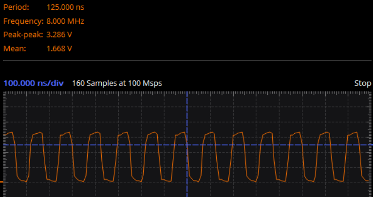
On this board, the MCO output from the debugging microcomputer is input to the OSC_IN terminal (pin 5), so check the circuit diagram.
When I checked the waveform, it was 8MHz as shown below. It matches the default value.
System Clock Mux
You can select the system clock from HSI, HSE, and PLL.
Of course, if you want to run at high frequencies, you should choose PLL.
Then, PCLK1 and PCLK2 are created from this output.
Which clock is used is determined by the peripheral.
Here You can see the table on page 39 of the Reference Manual (RM0368).
In the combo box marked with × 334 etc. (multiplication symbol), the number of multiplications of the PLL can be changed.
The combo box marked with / 4 etc. (with the division sign) allows you to divide the frequency.
It is possible to combine these to create an appropriate frequency.
If you make an unreasonable choice, that part will turn red and give you a warning.
The caveat to this board is that the System Clock Mux should be set to HSI if it is disconnected from the debugging microcomputer.
This board doesn’t have X3 installed, so you have to use HSI because you don’t have HSE.
I2S Source Mux
You can select the clock source to I2S from PLLI2SCLK or EXT clock.
This part is grayed out, so I2S clocks can be enabled by setting the Mode of I2S2 or I2S3 to something other than Disable in the neighboring Pinout & Configuration –Category –Multimedia.
Ext clock is enabled by checking Audio Clock Input (I2S_CKIN) of Pinout & Configuration –Category –System Core –RCC.
To check this, you need to uncheck Master Clock Output 2.
MCO1 source Mux
You can choose from LSE, HSE, HSI, PLLCLK.
To enable this, check Master Clock Output 1 in Pinout & Configuration –Category –System Core –RCC.
Although we have not confirmed the operation, this clock output is output from the PA8 terminal using the function of Alternate functions.
MCO2 source Mux
You can select from SYSCLK, PLLI2SCLK, HSE, PLLCLK.
To enable this, check Master Clock Output 2 in Pinout & Configuration –Category –System Core –RCC.
In order to check here, it is necessary to uncheck Audio Clock Input (I2S_CKIN).
Although we have not confirmed the operation, this clock output is output from the PC9 terminal using the function of Alternate functions.
Code generation
After changing the settings in Clock Configuration, the configurator will generate the initial clock configuration code by building.
This part of the code is implemented in SystemClock_Config () in main.c.
How was it? Did you understand the clock?
Thank you for your hard work.


