
This is another topic related to the STM32CubeIDE.
There is a useful feature called the configurator, which I will introduce here.
In this article, we will try to implement the timer interrupt function.
Development environment at the time of posting
PC: Windows 10 OS
IDE: STM32CubeIDE Version 1.1.0
Configurator: STM32CubeMX Version5.4.0
Board: STM32Nucleo-F401RE
In the Project Explorer, if the left side of the project name F401 is >, click on >.
The > will change to a V and you will see the hierarchy below the tree.
Double-click on the light blue icon F401.ioc to launch the Device Cofiguraiton Tool.
The tool consists of four tabs: Pinout & Configuration / Clock Configuration / Project Manager / Tools.
When the tool is launched, Pinout & Configuration is selected with a light blue background.
Click on Timers under Categories.
This time we will use TIM1 (Timer 1).
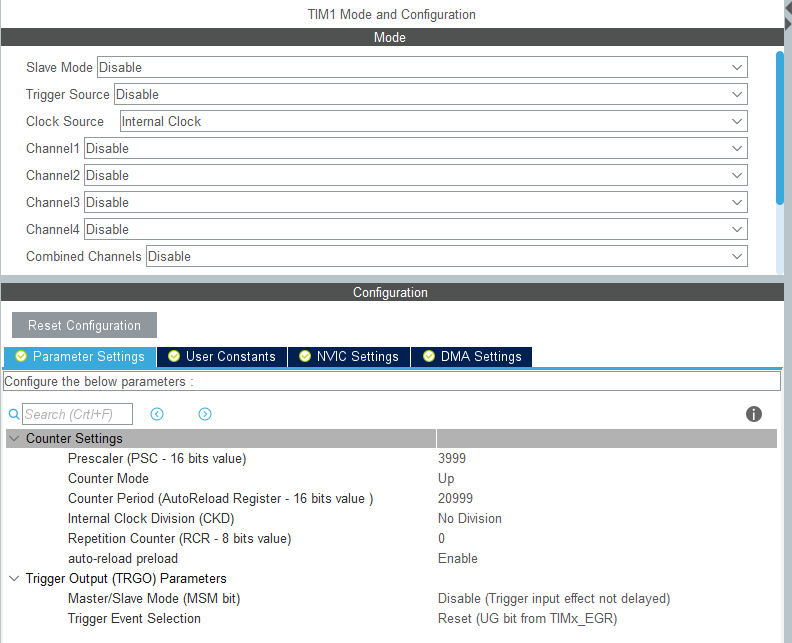
When you click TIM1, TIM1 Mode and Configuration will be displayed on the right side. If you select Internal Clock as Clock Source, the item will be displayed in the Configuraiton.
If you select Internal Clock as Clock Source, the item will appear in the Configuraiton.
Parameter Settings / User Constants / NVIC Settings / DMA Settings
When you click on an item with the mouse, the background color of the selected item will change to light blue.
Setting the timer cycle
With the Parameter Settings tab selected, we will now set the parameters.
Prescaler x Counter Period x 1/f = Timer Period.
The clock frequency is f = 84MHz.
If the prescaler is 4000 and the timer period is 1 second, the counter period will be 21000.
The prescaler and counter period are 16 bits, so make sure to set the value from 1 to 65535.
Then, set the auto reload to Enable.
Since the prescaler and counter period start counting at zero, the value to be set must be -1.
Each parameter should be set as follows.
Prescaler 3999
Counter Mode Up
Counter Period 20999
Internal Clock Division No Division
Reperirion Counter 0
Auto-reload preload Enable
Please refer to the following for a screenshot of the configuration.
Check the clock
Click on Clock Configuration (it’s the big tab on the top level) to see the clock system diagram.
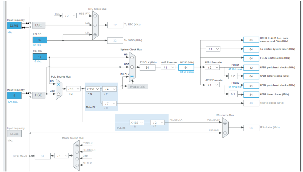
You can see that the APB1 and APB2 Timer clocks on the right side are set to 84MHz.
Which one is used for TIM1? I guess.
According to the datasheet, the clocks for each timer are as follows
APB1 : TIM2, 3, 4, 5
APB2 : TIM1, 9, 10, 11
But both clocks are 84MHz, so you don’t need to worry about it.
You can download the datasheet of the microcontroller on the board from the following link.
Allow Interrupts
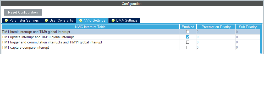
Select NVIC Settings in Configuration and check the Enable checkbox for TIM1 update interrupt and TIM10 global interrupt.
Coding it
Let’s build it once.
Select Project – Build All.
(Or, with F401 selected in the Project Explorer, select Project – Build Project)
You will be asked “Do you want generate Code ? Select Yes.
Make sure there are no build errors.
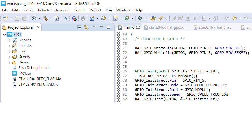
Double-click main.c in F401 > Core > Src in the Project Explorer.
In the main() function, a new function called MX_TIM1_Init(); has been added above while (1).
This MX_TIM1_Init() is the initialization function added by the configurator. The more peripheral functions are added, the more MX_xxx_Init() initialization functions are added.
The xxx part is an abbreviation for the peripheral function.
We can imagine that the MX comes from STM32CubeMX, a configurator that existed before the IDE was developed.
Double-click on MX_TIM1_Init() to select it, then right-click on it.
Select “Open Declaration” from the menu that appears.
Then you can jump to the implementation part of this function.
Implement the following code between USER CODE BEGIN and END at the end of the function.
Timer 1 will now start working.
/* USER CODE BEGIN TIM1_Init 2 */
HAL_TIM_Base_Start_IT(&htim1);
/* USER CODE END TIM1_Init 2 */
Next, implement the L-tica code to make sure that the timer interrupt is working.
In Project Explolre, go to F401 > Core > Startup, click the > on the left, and double-click startup_stm32f401retx.s. This file contains the interrupt vectors.
This file contains the interrupt vectors.
Select TIM1_UP_TIM10_IRQHandler on line 183, right-click it, and select Open Declaration.
A window will appear. Select stm32f4xx_it.c and click OK.
Implement HAL_GPIO_TogglePin() between “USER CODE BEGIN” and “USER CODE END”.
void TIM1_UP_TIM10_IRQHandler(void)
{
  /* USER CODE BEGIN TIM1_UP_TIM10_IRQn 0 */

  /* USER CODE END TIM1_UP_TIM10_IRQn 0 */
  HAL_TIM_IRQHandler(&htim1);
  /* USER CODE BEGIN TIM1_UP_TIM10_IRQn 1 */
  HAL_GPIO_TogglePin(GPIOA, GPIO_PIN_5);
  /* USER CODE END TIM1_UP_TIM10_IRQn 1 */
}
Build and run
Select Run – Debug.
If the code is implemented correctly, the program will wait at the HAL_Init() point of the main() function, so select Run – Resume.
If the code is implemented correctly, the green LED will blink every second.
By using the configurator, you can achieve the required functionality with very little code.
The IDE and the configurator are powerful tools, aren’t they?
I will start writing about serial communication in the next article.


