
In this article, we will continue with serial communication using interrupts.
The following is the development environment at the time of posting.
PC: Windows 10 OS
IDE: STM32CubeIDE Version1.1.0
Configurator: STM32CubeMX Version5.4.0
Board: STM32Nucleo-F401RE
Let’s see how the interrupt handling works
Now let’s follow how the interrupt handling works.
The interrupt controller is called NVIC.
The NVIC supports vector interrupts and branches to the addresses registered in the vector table for each interrupt or exception factor.
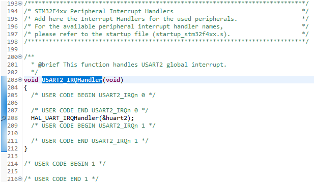
The interrupt vector for USART2 is written near line 203 in stm32f4xx_it.c.
Double click on the line number of HAL_UART_IRQHandler(&huart2); in the HAL_UART2_IRQHandler function to put a breakpoint.
Next, start up the terminal software on the PC.
Again, we will use Tera Term.
Start Tera Term, select “Serial” in “New connection”, and select the COM port number where the ST-Link Virturl COM port is displayed.
Set the communication parameters in the Setup – Serial port as follows

These values should match the values set by MX_USART2_UART_Init().
On the IDE side, run the program with Run – Resume.
Click on the Tera Term window to make it active, and press one key.
The data will be sent to you and the program will stop at the breakpoint.
Pressing the F5 key will step through the program, so you can see what is being done in the interrupt.
Stepping through the program, you will come to UART_Receive_IT(huart) in HAL_UART_IRQHandler.
*huart->pRxBuffPtr++ = (uint8_t)(huart->Instance->DR & (uint8_t)0x00FF);
Store the received data in the buffer in the line
Since this is the first reception (first byte), RxXferCount will be set to 1 in the next process, so the process in if() will not be executed.
if (–huart->RxXferCount == 0U)
{
…
}
Step by step, when you get out of if(), run the program again with Run – Resume.
Click on the Tera Term window to make it active, and press any one key again.
The program will come into the interrupt process and stop at the breakpoint. We will step through the process by pressing the F5 key.
Since this is the second (second byte) received, RxXferCount will be set to 0 in the next process and the process in if() will be executed.
if (–huart->RxXferCount == 0U)
{
…
}
After disabling the receive interrupt, HAL_UART_RxCpltCallback is called.
Since we set gUartReceive = 1, HAL_UART_Transmit_IT(&huart2, buffer, 2); is executed after exiting the while() loop in the main function.
Let’s release the breakpoint and run the program with Run – Resume.
(To release a breakpoint, double-click on the line number of the line where the breakpoint was placed.
Transmit interrupt processing
In HAL_UART_Transmit_IT
huart->pTxBuffPtr = pData;
huart->TxXferSize = Size;
huart->TxXferCount = Size;
__HAL_UART_ENABLE_IT(huart, UART_IT_TXE);
The code is written as shown in the following example, where the first address of the buffer is set to the transmit buffer pointer in the structure.
Then, the size of the data to be sent is set in the size and counter variables.
The interrupt vector is USART2.
Since the interrupt vector is for USART2, it is the same for both transmit and receive.
USART2_IRQHandler ~ HAL_UART_IRQHandler will be called.
Then UART_Transmit_IT is called to send the data.
Since this is the first transmission (first byte), TxXferCount will be set to 1 in the next process, so the process in if() will not be executed.
if (--huart->TxXferCount == 0U)
{
      __HAL_UART_DISABLE_IT(huart, UART_IT_TXE);
      __HAL_UART_ENABLE_IT(huart, UART_IT_TC);
}
After the second transmission (second byte), TxXferCount will be set to 0, the process in if() will be executed and the transmit interrupt will be disabled.
The received buffer contains the sent data, which is sent back to the receiver.
If the two characters sent by Tera Term are looped back and displayed, it is a success.


