
In this article, I will write about communication using I2C.
The following is the development environment at the time of submission.
PC: Windows 10 OS
IDE: STM32CubeIDE Version1.3.0
Configurator: STM32CubeMX Version 5.5.0
Board: STM32Nucleo-F401RE
Overview of I2C communication
A communication method developed by Philips (now NXP) Semiconductors.
Two communication lines, SCL and SDA, for bi-directional communication
There are several options for communication speed, such as 100k, 1Mbits/sec, etc.
There are master and slave devices, and a multi-master system is possible.
For more information about I2C, please refer to here.
Target to be a slave
I used the STM32 (controlled by the master) and the following devices for the slaves.
barometric pressure sensor module.
This is sold at Akizuki Denshi, a well-established company in Akihabara, Japan.
The price is 600 Japanese yen. I bought it using the Internet.
I am afraid it is made in Japan, but I want to blog about the results of checking the operation.
The manufacturer is STMicro. The datasheet of the device is here.
Solder two soldering jumpers to put pull-up resistors on SCL and SDA lines.
Connection
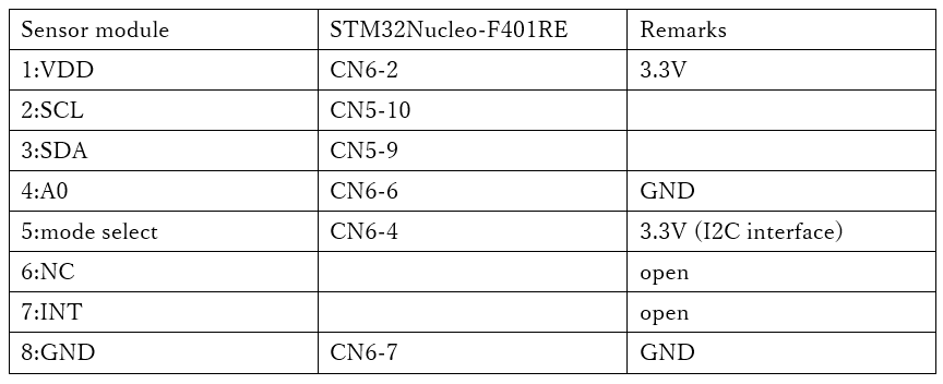
Make the connections as shown in the table below.
You can select the interface on pin 5 whether you want to connect this module via I2C or SPI.
Since we will be using I2C, connect pin 5 to H (3.3V).
Pin 4 is the least significant bit of the device address. Now you can connect two devices to the same device, but since we are using only one, connect it to L (GND).
We do not use interrupts, so we do not connect the INT pin.
Create a project
Start the IDE, select File- New – STM32 Project, when the Target Selection window comes up, select the Board Selector tab, select NUCLEO-F401RE from the Boards List and press the Next button.
Enter F401I2cHAL as the Project name and press the Finish button.
When it asks “Initialize all peripherals with their default Mode ? Press Yes.
This kind of project is associated with the STM32CubeMx perspective. Do you want to open this perspective now ? Press Yes.
Adding the I2C interface in the code generator
The I2C pins we will use are PB8 and PB9. (The area circled in red near the top left of the image)
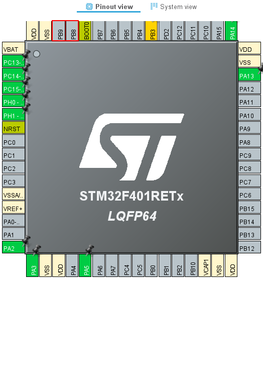
Right-click on PB8 to select it, then select I2C1_SCL.
Right-click on PB9 to select it, and then select I2C1_SDA.
Make sure that the color of the pin changes from gray to yellow.
Then select Pinout & Configuration – Categories – Connectivity – I2C1
Select I2C from the list of I2C in I2C1 Mode and Configuration – Mode.
Select F401I2cHAL in the Project Explorer and build it in Project – Build Project.
The color of the pins will change from yellow to green.
Also, make sure that MX_I2C1_Init() is generated in main.c.
Add the code
I wrote the code to be completed within the MX_I2C1_Init() function.
static void MX_I2C1_Init(void)
{

  /* USER CODE BEGIN I2C1_Init 0 */

#define WHO_AM_I 0x0f
#define CTRL_REG1 0x20
#define WAKE_UP 0x90
#define P_ADRS 0x28

  HAL_StatusTypeDef s;
  uint8_t err;
  uint8_t buf[16];
  uint32_t press;

  /* USER CODE END I2C1_Init 0 */

  /* USER CODE BEGIN I2C1_Init 1 */ /* USER CODE END I2C1_Init 2

  /* USER CODE END I2C1_Init 1 */ /* USER CODE
  Instance = I2C1;
  Init.ClockSpeed = 100000;
  Init.DutyCycle = I2C_DUTYCYCLE_2;
  Init.OwnAddress1 = 0;
  Init.AddressingMode = I2C_ADDRESSINGMODE_7BIT;
  Init.DualAddressMode = I2C_DUALADDRESS_DISABLE;
  Init.OwnAddress2 = 0;
  Init.GeneralCallMode = I2C_GENERALCALL_DISABLE;
  Init.NoStretchMode = I2C_NOSTRETCH_DISABLE;
  if (HAL_I2C_Init(&hi2c1) ! = HAL_OK)
  {
    Error_Handler();
  }
  /* USER CODE BEGIN I2C1_Init 2 */ buf[0] = WHO_AM_I; // Who am I?

  buf[0] = WHO_AM_I; // Who am I ?

  s = HAL_I2C_Master_Transmit(&hi2c1, 0xb8, buf, 2, 3000);
  s = HAL_I2C_Master_Receive(&hi2c1, 0xb9, buf, 1, 3000);

  if (HAL_OK == s)
  {
	  if (0xbd == buf[0])
	  {
		  err = 0;
	  }
	  } else
	  {
		  err = 1;
	  }

  }
  } else
  {
	  err = 1;
  }

  buf[0] = CTRL_REG1; // Control Register1
  buf[1] = WAKE_UP;

  s = HAL_I2C_Master_Transmit(&hi2c1, 0xb8, buf, 2, 3000);

  HAL_Delay(1000);

  buf[0] = P_ADRS | 0x80;

  s = HAL_I2C_Master_Transmit(&hi2c1, 0xb8, buf, 1, 3000);
  s = HAL_I2C_Master_Receive(&hi2c1, 0xb9, buf, 3, 3000);

  press = buf[2] << 16 | buf[1] << 8 | buf[0];
  press /= 4096;

  /* USER CODE END I2C1_Init 2 */ buf[2] << 16 | buf[1] << 8 | buf[0]; press /= 4096

}
Explanation of the code
Read the value of the register WHO_AM_I, and if it is 0xbd, then the device is recognized.
Write WAKE_UP(0x90) in control register 1 to release the power down mode.
Read the barometric pressure measurements from the registers 0x28 (P_ADRS), 0x29, and 0x2a.
By setting P_ADRS | 0x80, the address can be auto-incremented and read one after another.
By dividing the read value by 4096, the barometric pressure in units [hPa] can be obtained.
The barometric pressure I read and calculated was 1009 or 1010 [hPa].


