
In this article, I will try to use I2C communication with Mbed.
I wrote an article about I2C using HAL in here, but this time I wrote about the case using Mbed.
Here is the development environment at the time of posting.
PC: Windows 10 OS
IDE: STM32CubeIDE Version1.3.0
Board: STM32Nucleo-F401RE
Outline of I2C communication
A communication method developed by Philips (now NXP) Semiconductors.
Two communication lines, SCL and SDA, for bi-directional communication
There are several options for communication speed, such as 100k, 1Mbits/sec, etc.
There are master and slave devices, and a multi-master system is possible.
For more information about I2C, please refer to here.
Target to be a slave
I used the STM32 (the master) to control the device and the slave devices are the following
barometric pressure sensor module.
This is sold at Akizuki Denshi, a well-established company in Akihabara, Japan.
The price is 600 Japanese yen. I bought it using the Internet.
I am afraid it is made in Japan, but I want to blog about the results of checking the operation.
The manufacturer is STMicro. The datasheet of the device is here.
Solder two soldering jumpers to put pull-up resistors on SCL and SDA lines.
Connection
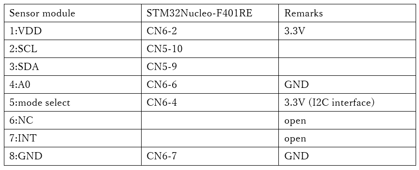
Make the connections as shown in the table below.
You can select the interface on pin 5 whether you want to connect this module via I2C or SPI.
Since we will be using I2C, connect pin 5 to H (3.3V).
Pin 4 is the least significant bit of the device address. Now you can connect two devices to the same device, but since we are using only one, connect it to L (GND).
We do not use interrupts, so we do not connect the INT pin.
Download Mbed project
If you want to try to use Mbed in C++, you can download the following project.
Let’s try coding
I referred to the site here for how to use I2C in Mbed.
The timer needs to be initialized, so write the code after SystemClock_Config() in the maini() function.
 /* Configure the system clock */
  SystemClock_Config();

  /* USER CODE BEGIN SysInit */

  /* USER CODE END SysInit */

  /* Initialize all configured peripherals */ MX_GPIO_Init()
  MX_GPIO_Init();
  MX_USART2_UART_Init();

  /* USER CODE BEGIN 2 */ /* USER CODE END SysInit

#define WHO_AM_I 0x0f
#define CTRL_REG1 0x20
#define WAKE_UP 0x90
#define P_ADRS 0x28

  int err;
  char buf[16];
  uint32_t press;

  I2C i2c(I2C_SDA, I2C_SCL);

  buf[0] = WHO_AM_I; // Who am I ?

  i2c.write(0xb8, (const char*)buf, 1);
  i2c.read(0xb9, buf, 1);

  if (0xbd == buf[0])
  {
    err = 0;
  }
  else
  {
    err = 1;
  }

  buf[0] = CTRL_REG1; // Control Register1
  buf[1] = WAKE_UP;

  i2c.write(0xb8, (const char*)buf, 2);

  buf[0] = P_ADRS | 0x80;

  i2c.write(0xb8, (const char*)buf, 1);

  i2c.read(0xb9, buf, 3);

  press = buf[2] << 16 | buf[1] << 8 | buf[0];
  press /= 4096;
Explanation of the code
Using Mbed is easy and hassle-free because the initialization is done in the constructor.
Read the value of the register WHO_AM_I, and if it is 0xbd, then the device is recognized.
Write WAKE_UP(0x90) to control register 1 to release the power down mode.
Read the barometric pressure measurements from the registers 0x28 (P_ADRS), 0x29, and 0x2a.
By setting P_ADRS | 0x80, the address can be auto-incremented and read one after another.
By dividing the read value by 4096, the barometric pressure in units [hPa] can be obtained.
The barometric pressure was 1014 [hPa].


