In this article, I will talk about the pin alternate function using HAL.
The following is the development environment at the time of posting.
PC: Windows 10 OS
IDE: STM32CubeIDE Version1.3.0
Configurator: STM32CubeMX Version 5.5.0
Board: STM32Nucleo-F401RE
What is the pin alternate function?
In a typical microcontroller, the function of pin number “△△” of a package is defined as “〇〇”.
In the case of the STM32, we can say “this pin number is assigned this function”.
However, this doesn’t mean that you can set everything up freely, but rather that you have a few options from the predetermined specifications.
Well, it’s not so much very convenient as it is binding.
Still, knowing this feature can be useful when designing a circuit.
The board we will be using is an STM32Nucleo-F401RE.
The datasheet for the microcontroller used on this board can be found here.
Take a look at Table 9. Alternate function mapping in this document.
For example, the pins of Port PA9 are
TIM1_CH2, I2C3_SMBA, USART1_TX, OTG_FS_VBUS, EVENTOUT
functions.
Depending on the configuration, it is possible to decide which of these functions should be used for this pin (terminal).
Let’s check the Alternate function using serial communication as an example.
From the datasheet, we can see that USART1 belongs to the group AF07.
If you look for USART1_TX in AF07, you will see that it is assigned to PA9 and PB6.
Let’s say that you really want to use PA9 as TIM1_CH2.
If you really want to use PA9 as TIM1_CH2, and you also want to use USART1_TX, you can assign USART1_TX to PB6.
Let’s try it out for ourselves.
Create a project
Launch the IDE and select File – New – STM32 Project.
In the Board Selecter, select NUCLEO-F401RE and press Next.
Enter AlternateTest as the Project Name and press Finish.
When it asks “Initialize all peripherals with their default Mode ? and press Yes.
(Do you want to initialize all peripherals with their default Mode?
This kind of project is associated with the STM32CubeMx perspective.
Press Yes when it asks “Do you want to open this perspective now?
(This kind of project is associated with the STM32CubeMx perspective. Do you want to open it now?
I’m not sure what this means, but I interpreted it as “Do you want to import the configurator STM32CubeMX into the IDE layout? I interpreted it as “Do you want to import the STM32CubeMX configurator into the IDE layout?
Now we have a project that initializes the peripherals with certain specifications for this board.
Without comments, the contents of the main() function are as follows
int main(void)
{
  HAL_Init();
  SystemClock_Config();
  MX_GPIO_Init();
  MX_USART2_UART_Init();
  while (1)
  {
  }
}
At this stage, the USART1_TX function is not enabled.
Double-click AlternateTest.ioc in the Project Explorer to display the microcontroller package.
This is where the configurator functions.
The PA9 and PB6 pins here are grayed out, indicating that the functions of these pins are not being used.
Click on PA9 in the right column and select USART1_TX from the list.
The color of the pin has changed from gray to yellow.
Next, select Categories – Connectivity – USART1 from Pinout & Configuraiton and select Asynchronous for Mode.
In the Project Explorer, select AlternateTest, and then Project – Build Project.
When it asks “Do you want generate Code ? and press Yes.
This asks if you want to generate the initialization code with the STM32CubeMX function. This is the inquiry.
Then PA9 turns from yellow to green, and PA10 USART1_RX next to it also turns green.
It seems that transmit and receive have to be used in pairs.
Checking in main(), MX_USART1_UART_Init() has been added.
The initialization process of USART1 has been added by the configurator.
Connecting pins and functions
Now let’s see how the USART1 is connected to the configured pins.
In ProjectExplorer, double click on the file Core – Src – stm32f4xx_hal_msp.c to open it.
The pin settings are done in the function HAL_UART_MspInit().
MSP stands for MCU Support Package.
void HAL_UART_MspInit(UART_HandleTypeDef* huart)
{
  GPIO_InitTypeDef GPIO_InitStruct = {0}
  if(huart->Instance==USART1)
  {
  /* USER CODE BEGIN USART1_MspInit 0 */

  /* USER CODE END USART1_MspInit 0 */
    /* Peripheral clock enable */
    __HAL_RCC_USART1_CLK_ENABLE();

    __HAL_RCC_GPIOA_CLK_ENABLE();
    /**USART1 GPIO Configuration
    PA9 ------> USART1_TX
    PA10 ------> USART1_RX
    */ GPIO_InitStruct.
    GPIO_InitStruct.Pin = GPIO_PIN_9|GPIO_PIN_10;
    GPIO_InitStruct.Mode = GPIO_MODE_AF_PP;
    GPIO_InitStruct.Pull = GPIO_NOPULL;
    GPIO_InitStruct.Speed = GPIO_SPEED_FREQ_VERY_HIGH;
    GPIO_InitStruct.Alternate = GPIO_AF7_USART1;
    HAL_GPIO_Init(GPIOA, &GPIO_InitStruct);

(Omitted after that.)
The configurator initializes the GPIOs with the HAL_GPIO_Init() function.
The first argument specifies the port. In this case, it is GPIOA.
The second argument specifies the structure address for GPIO initialization.
The GPIO_INitStruct.Pin member is used to set the pin for this port.
If the settings of the pins are the same, you can set them all together by taking OR with | and specifying multiple bits.
Since PA9 is USART1_TX and PA10 is USART1_RX, we OR 9 and 10 to set them at the same time.
Then, by setting GPIO_InitStruct.Alternate = GPIO_AF7_USART1, we can use these pins as a function of USART1.
GPIO_AF7_USART1 is defined in Drivers/STM32F4xx_HAL_Driver/Inc/stm32f4xx_hal_gpio_ex.h.
Various peripherals are also defined, so please check them out.
USB Serial Conversion Module
We used a USB serial conversion module to check the serial communication between the PC and the microcontroller.
This module uses a device called FT234XD from FTDI.
For more information, please see here.
Sorry, it’s from a Japanese manufacturer.
Images of the connection
Connect with a cross as shown below.

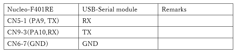
Connection
Connect the STM32Nucleo-F401RE to the USB serial converter module as shown in the table below.
Let’s code it
Now let’s implement the communication part of the program.
First, define the variables at the beginning of main().
int main(void)
{
  /* USER CODE BEGIN 1 */ uint8_t buffer[256
  uint8_t buffer[256];
  HAL_StatusTypeDef s;
  /* USER CODE END 1 */ /* USER CODE BEGIN 1 */ uint8_t buffer[256]; HAL_StatusTypeDef s
.
Next, please describe the while() loop part as follows.
/* USER CODE BEGIN WHILE */ /* USER CODE END 1 */ After the coding is done, build it and make sure there are no errors.
Preparation for PC side
Again, we will use Tera Term.
Start Tera Term, select Serial port in the startup connection, and select USB serial COM as the port.
Setup – Serial port and set the parameters as follows
Speed : 115200
Data : 8
Parity: none
Stop bit : 1bit
Flow control: none
Make sure that these parameters match the UART settings output by the configurator.
Verify the operation
From the IDE, Run – Debug, press F8 (Resume) to run the program.
Press any key from Tera Term to send one character at a time.
The board will return what it receives, so if the key pressed by Tera Term is displayed, the program is successful.
If nothing is sent for 10 seconds, “UART Timeout.” is displayed.
Switching pins
This is a part that should be done by the configurator, so I probably shouldn’t touch it, but it’s an experiment.
Since we are switching the transmit pin from PA9 to PB6, we will rewrite the USART1 part of HAL_UART_MspInit() as follows.
Also enable the GPIOB clock.
if(huart->Instance==USART1)
{
__HAL_RCC_USART1_CLK_ENABLE();
__HAL_RCC_GPIOA_CLK_ENABLE();
__HAL_RCC_GPIOB_CLK_ENABLE();
GPIO_InitStruct.Pin = GPIO_PIN_10;
GPIO_InitStruct.Mode = GPIO_MODE_AF_PP;
GPIO_InitStruct.Pull = GPIO_NOPULL;
GPIO_InitStruct.Speed = GPIO_SPEED_FREQ_VERY_HIGH;
GPIO_InitStruct.Alternate = GPIO_AF7_USART1;
HAL_GPIO_Init(GPIOA, &GPIO_InitStruct);
GPIO_InitStruct.Pin = GPIO_PIN_6;
GPIO_InitStruct.Mode = GPIO_MODE_AF_PP;
GPIO_InitStruct.Pull = GPIO_NOPULL;
GPIO_InitStruct.Speed = GPIO_SPEED_FREQ_VERY_HIGH;
GPIO_InitStruct.Alternate = GPIO_AF7_USART1;
HAL_GPIO_Init(GPIOB, &GPIO_InitStruct);
}
Build it and make sure there are no errors.
Then replace the transmit side of the USB serial converter from PA9 to PB6.
On the terminal, reconnect the wire connected to CN5-1 of the Nucleo-F401RE to CN5-3.
Run the program in the IDE and confirm that Tera Term returns the data you sent.
How did you like it?
You can use the alternate function not only for USART but also for various other veriferals.
Please give it a try.


