
I have written an article on I2C communication before, and this time I would like to write about SPI communication with a similar interface.
The following is the development environment at the time of submission.
PC: Windows 10 OS
IDE: STM32CubeIDE Version1.3.0
Configurator: STM32CubeMX Version5.5.0
Board: STM32Nucleo-F401RE
Overview of SPI communication
SPI stands for Serial Peripheral Interface.
Like I2C, it is a way to communicate between a microcontroller and peripheral devices (in general) on a printed circuit board.
While I2C has a single data bus for both transmission and reception, SPI has a separate data bus.
This means that full-duplex communication is possible, and therefore the communication speed is faster.
Communication methods developed by Motorola
Four communication lines (SCK, MISO, MOSI, and SS) can be used for bi-directional communication.
Communication speed is faster than I2C.
There is a master and a slave.
For more information about SPI, please refer to here.
Targets that are slaves
I used the STM32 (controlled by the master) and the following devices for the slaves.
barometric pressure sensor module.
The price is japanese 600 yen and I bought it using the internet.
I am afraid it is made in Japan, but I want to blog about the results of checking the operation.
The manufacturer is STMicro. The datasheet for the device is here.
Connection
The connections are as shown in the table below.
You can choose whether you want to connect this module via I2C or SPI.
Since we will be using SPI, we will connect pin 5 to the chip select signal.
Since we will not be using interrupts, we have not connected the INT pin.
For SPI communication, the J1 and J2 solder jumpers on the back side must be open.

Create a project
Start the IDE, select File- New – STM32 Project, when the Target Selection window comes up, select the Board Selector tab, select NUCLEO-F401RE from the Boards List and press the Next button.
Enter F401SPiHAL as the Project Name and press the Finish button.
When it asks “Initialize all peripherals with their default Mode ? Press Yes.
This kind of project is associated with the STM32CubeMx perspective. Do you want to open this perspective now ? Press Yes.
Adding the SPI interface in the code generator
.
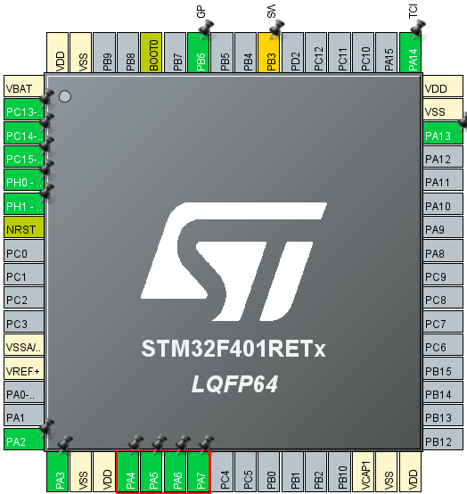
The SPI pins we will use are PA4, 5, 6, and 7. (The area circled in red near the top left of the image)
Right-click on PA4 to select it, then select GPIO_Output.
Right-click on PA5 to select it, and select SPI1_SCK.
Right-click and select PA6, then select SPI1_MISO.
Right-click on PA7 to select it and choose SPI1_MOSI.
Then select Pinout & Configuration – Categories – Connectivity – SPI1
Select Full Duplex Master from the list of SPI1 Mode and Configuration – Mode.
Leave the Hardware NSS Signal disabled.
Select F401SPiHAL in the Project Explorer and build it with Project – Build Project.
Verify that MX_SPI1_Init() is generated in main.c and there are no errors.
Add the code
I wrote the code to be completed within the MX_SPI1_Init() function.
static void MX_SPI1_Init(void)
{

  /* USER CODE BEGIN SPI1_Init 0 */
#define WHO_AM_I 0x0f
#define CTRL_REG1 0x20
#define WAKE_UP 0x90
#define P_ADRS 0x28

  HAL_StatusTypeDef s;
  uint8_t err;
  uint8_t sbuf[16], rbuf[16];
  uint32_t press;

  /* USER CODE END SPI1_Init 0 */

  /* USER CODE BEGIN SPI1_Init 1 */ /* USER CODE

  /* USER CODE END SPI1_Init 1 */ /* SPI1 parameter configuration*//
  /* SPI1 parameter configuration*/
  hspi1.Instance = SPI1;
  hspi1.Init.Mode = SPI_MODE_MASTER;
  hspi1.Init.Direction = SPI_DIRECTION_2LINES;
  hspi1.Init.DataSize = SPI_DATASIZE_8BIT;
  hspi1.Init.CLKPolarity = SPI_POLARITY_HIGH;
  hspi1.Init.CLKPhase = SPI_PHASE_2EDGE;
  hspi1.Init.NSS = SPI_NSS_SOFT;
  hspi1.Init.BaudRatePrescaler = SPI_BAUDRATEPRESCALER_64;
  hspi1.Init.FirstBit = SPI_FIRSTBIT_MSB;
  hspi1.Init.TIMode = SPI_TIMODE_DISABLE;
  hspi1.Init.CRCCalculation = SPI_CRCCALCULATION_DISABLE;
  hspi1.Init.CRCPolynomial = 10;
  if (HAL_SPI_Init(&hspi1) != HAL_OK)
  {
    Error_Handler();
  }
  /* USER CODE BEGIN SPI1_Init 2 */

  sbuf[0] = WHO_AM_I | 0x80; // Who am I ?
  sbuf[1] = 0x00;

  rbuf[0] = rbuf[1] = 0x00;

  HAL_GPIO_WritePin(GPIOA, GPIO_PIN_4, GPIO_PIN_RESET);
  s = HAL_SPI_TransmitReceive(&hspi1, sbuf, rbuf, 2, 1000);
  HAL_GPIO_WritePin(GPIOA, GPIO_PIN_4, GPIO_PIN_SET);

  if (HAL_OK == s)
  {
    if (0xbd == rbuf[1])
    {
      err = 0;
    }
    else
    {
      err = 1;
    }
  }
  else
  {
    err = 1;
  }

  sbuf[0] = CTRL_REG1; // Control Register1
  sbuf[1] = WAKE_UP;

  HAL_GPIO_WritePin(GPIOA, GPIO_PIN_4, GPIO_PIN_RESET);
  s = HAL_SPI_TransmitReceive(&hspi1, sbuf, rbuf, 2, 1000);
  HAL_GPIO_WritePin(GPIOA, GPIO_PIN_4, GPIO_PIN_SET);

  HAL_Delay(1000);

  sbuf[0] = P_ADRS | 0xc0;

  HAL_GPIO_WritePin(GPIOA, GPIO_PIN_4, GPIO_PIN_RESET);
  s = HAL_SPI_TransmitReceive(&hspi1, sbuf, rbuf, 4, 1000);
  HAL_GPIO_WritePin(GPIOA, GPIO_PIN_4, GPIO_PIN_SET);

  press = rbuf[3] << 16 | rbuf[2] << 8 | rbuf[1];
  press /= 4096;

  /* USER CODE END SPI1_Init 2 */ rbuf[1] << 16

}
Code description
I made the following settings according to the specification of the barometric sensor, and checked the operation, and WHO_AM_I was read without any problem.
( CPOL=1, CPHA=1, so mode=3, as per the specification of the barometric sensor )
hspi1.Init.CLKPolarity = SPI_POLARITY_HIGH; // CPOL=1
hspi1.Init.CLKPhase = SPI_PHASE_2EDGE; // CPHA=1
HAL_GPIO_WritePin(GPIOA, GPIO_PIN_4, GPIO_PIN_SET);

__HAL_SPI_ENABLE(&hspi1);

HAL_GPIO_WritePin(GPIOA, GPIO_PIN_4, GPIO_PIN_RESET);
s = HAL_SPI_TransmitReceive(&hspi1, sbuf, rbuf, 2, 1000);
HAL_GPIO_WritePin(GPIOA, GPIO_PIN_4, GPIO_PIN_SET);

if (HAL_OK == s)
{
  if (0xbd == rbuf[1])
In the HAL_SPI_TransmitReceive() function, there is the following process.
Only the first time, it seems to go through this if().
This process of enabling SPI causes the clock to run.
As a countermeasure, I added a process to enable SPI before setting CS=L.
if ((hspi->Instance->CR1 & SPI_CR1_SPE) ! = SPI_CR1_SPE)
{
__HAL_SPI_ENABLE(hspi);
}
There is also a way to control the chip select signal with hardware, but it seems to be inflexible, so I decided to use GPIO (PA4) to control it.
The communication process is divided into two parts: HAL_GPIO_WritePin(GPIOA, GPIO_PIN_4, GPIO_PIN_RESET) and
HAL_GPIO_WritePin(GPIOA, GPIO_PIN_4, GPIO_PIN_SET).
First read the value of the register WHO_AM_I, if it is 0xbd, then the device is recognized.
Next, write WAKE_UP(0x90) to control register 1 to release the power down mode.
The barometric pressure readings are taken from the registers 0x28 (P_ADRS), 0x29, and 0x2a.
To read the register values from the data sheet, first send the register values plus 0x80 or.
Since it takes 8 clocks to send the register value and then 8 clocks to read it, HAL_SPI_TransmitReceive()
The fourth argument should be set to 2.
Then write WAKE_UP (0x90) to the control register.
Do not set 0x80 or during the write operation.
Again, it takes 8 clocks to send the value of the register and then 8 clocks to send the value to be written to it.
Therefore, the fourth argument of HAL_SPI_TransmitReceive() should be set to 2 as well.
Now that the barometric pressure sensor has started working, wait for one second and then read the barometric pressure value.
By setting 0xc0 or in the register P_ADRS, the address of the register can be read one after another while auto-incrementing.
(When reading, set 0x80 or, and to auto-increment the register, set 0x40 or.
Since it takes 8 clocks to send the register value and 24 clocks to read those 3 bytes afterwards, HAL_SPI_TransmitReceive()
The fourth argument is set to 4.
The read value comes in from rbuf[1].
Divide the read value by 4096 to get the air pressure in units [hPa].
The barometric pressure was 1014 [hPa].


