
In this article, I will talk about AD conversion.
The following is the development environment at the time of posting.
PC: Windows 10 OS
IDE: STM32CubeIDE Version1.3.0
Configurator: STM32CubeMX Version 5.5.0
Board: STM32Nucleo-F401RE
What is an ADC?
ADC stands for Analog to Digital Converter and it converts an analog voltage into a digital one.
In this example, we will read the voltage applied to a variable resistor and convert it to a digital value.
Connection
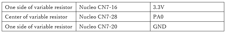
Make the connections as shown in the table below.
The constant of the variable resistor can be whatever you want.
I used a 2kΩ one that I had on hand.
Connect the center of the variable resistor to the PA0 pin to read the analog voltage.
Connect the remaining two pins of the variable resistor to 3.3V and GND.
This can be done with either leg connected to 3.3V.
(The only difference is that turning the variable resistor to the right will increase or decrease the voltage.
Make sure you don’t accidentally short 3.3V to GND.
Create a project
Start the IDE, select File- New – STM32 Project, when the Target Selection window comes up, select the Board Selector tab, select NUCLEO-F401RE from the Boards List and press the Next button.
Enter F401ADcHAL as the Project Name and press the Finish button.
When it asks “Initialize all peripherals with their default Mode ? Press Yes.
This kind of project is associated with the STM32CubeMx perspective. Do you want to open this perspective now ? Press Yes.
Configuring the ADC in the code generator
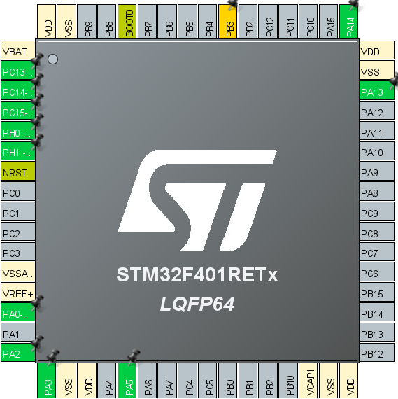
The pin we are going to configure is PA0 on the left.
Right-click on PA0 and select ADC1_IN0 from the list.
This will set this pin as the input pin for the ADC.
Select F401ADcHAL in the Project Explorer and build it under Project – Build Project.
Make sure that MX_ADC1_Init() is generated in main.c and there are no errors.
Adding the code
Declare the variables under main().
int main(void)
{
  /* USER CODE BEGIN 1 */
  __IO uint32_t ad;
  double v;

  /* USER CODE END 1 */ __IO
Implement the AD conversion process in the while() loop.
 /* USER CODE BEGIN WHILE */
  while (1)
  {
    /* USER CODE END WHILE */
    /* USER CODE BEGIN 3 */
    HAL_ADC_Start(&hadc1);
    if( HAL_ADC_PollForConversion(&hadc1, 1000) == HAL_OK )
    {
	ad = HAL_ADC_GetValue(&hadc1);
        v = 3.3 * ad / 4095;
    }
    HAL_ADC_Stop(&hadc1);
  }
  /* USER CODE END 3 */
Build it and make sure there are no errors.
Explanation of the code
About __IO attribute:
Double-click on __IO to select it, and select Open Declaration from the right-click menu.
#define __IO Jump to the definition of volatile. The true identity of __IO was volatile.
Volatile means “changeable, unstable”.
It means “changeable” or “unstable”, and it’s a way of telling the compiler that it’s going to change.
The __IO is a modifier that tells the compiler not to perform optimizations.
HAL_ADC_GetValue() is a function that returns the value of a register, and the value of the register will naturally change if the input of the AD conversion changes.
The value of the register will naturally change if the input of the AD conversion changes, but the compiler does not understand this and may interpret the value as always being the same due to optimization.
To avoid this problem, we will instruct the compiler not to perform optimization.
First, start AD conversion with HAL_ADC_Start(), and then
HAL_ADC_PollForConversion() waits for the completion of AD conversion.
When HAL_OK is obtained, read the value with HAL_ADC_GetValue(), and then stop the conversion with HAL_ADC_Stop().
The resolution of the AD conversion can be selected from 12, 10, 8, or 6.
In the code output by the configurator, 12 bits is selected.
Looking at the circuit diagram, the VREF+ input is connected to VDD (3.3V) via an inductor, so if you turn the variable resistor all the way to the positive (VDD) side, the input voltage to the PA0 pin will be close to VREF+, and the converted value will be close to 4095.
(Since it is 12 bits, the maximum value, 1111 1111 1111 in binary, is 4095 in decimal.)
Also, if you turn it to the ground side, the converted value will be close to 0.
If you adjust it to the center, you will get a value around 2000.
Run the program, and while turning the variable resistor, stop at the appropriate timing at the part ad = HAL_ADC_GetValue(&hadc1); and read the value of ad.
Also, since the 12-bit value doesn’t ring a bell, I converted it to a voltage using the following formula to get v.
v = 3.3 * ad / 4095;
If you get the value you expect, you have succeeded.


