In this article, we will try to process serial communication transmission using DMA.
The following is a description of the development environment at the time of submission.
PC: Windows 10 OS
IDE: STM32CubeIDE Version1.3.0
Configurator: STM32CubeMX Version5.5.0
Board: STM32Nucleo-F401RE
Overview of DMA
DMA stands for Direct Memory Access.
Normally, data is read from the peripheral (peripheral I/O) into memory via the CPU, and data is written from memory to the peripheral via the CPU.
With DMA, the memory is literally accessed directly, eliminating the need to go through the CPU, and the time can be used for other processing.
On the other hand, if the number of data (bytes) to be read or written is fixed, the processing is easy, but if it is not, there is a risk that the processing will become complicated.
For example, in the UART reception process, even if the number of data to be sent is fixed, the number of data may become unscheduled due to errors or omissions depending on the communication environment.
In this section, we will not handle the complicated receiving process with DMA, but will only check the operation of DMA for the sending process, which is relatively easy to handle.
Creating a project
Start the IDE, select File- New – STM32 Project, when the Target Selection window comes up, select the Board Selector tab, select NUCLEO-F401RE from the Boards List and press Next.
Enter F401UartDMA as the Project Name and press the Finish button.
When it asks “Initialize all peripherals with their default Mode ? Press Yes.
This kind of project is associated with the STM32CubeMx perspective. Do you want to open this perspective now ? Press Yes.
Configure the configurator
Click USART2 under Connectivity on the left, then click DMA Settings on the right.
Click the Add button in the lower left corner and set Select to USART2_TX in the combo box that comes up.
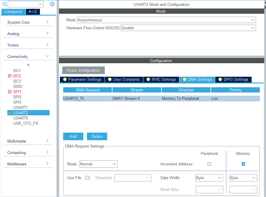
Then, in Parameter Settings, change the Baud Rate to 1200bps.
Leave the rest of the settings as they are (below).
Data: 8bit
Parity: none
Stop bit: 1bit
Flow control: none
Note that if the settings are different between the sending and receiving sides, communication will not work properly.
Select F401UartDMA in the Project Explorer and build it once in Project – Build Project to make sure there are no errors.
If a query window comes up, press Yes.
Coding
In the Project Explorer, double-click on F401UartDMA – Core – Src – main.c to open the file.
First, describe the variables as follows
int main(void)
{ main(void)
  /* USER CODE BEGIN 1 */
  uint8_t buffer[16];
  uint32_t t1, t2, t3, t4;
  /* USER CODE END 1 */
Next, code the while loop part as follows.
/* USER CODE BEGIN WHILE */
  buffer[0] = 'a';
  for (i = 1; i < 10; i++)
  {
	  buffer[i] = buffer[i - 1] + 1;
  }
  while (1)
  {

	t1 = HAL_GetTick();
	HAL_UART_Transmit(&huart2, buffer, 10, 1000);
	t2 = HAL_GetTick();
	t3 = t2 - t1;

	HAL_Delay(1000);

	t1 = HAL_GetTick();
	HAL_UART_Transmit_DMA(&huart2, buffer, 10);
	t2 = HAL_GetTick();
	t4 = t2 - t1;

	HAL_Delay(1000);

    /* USER CODE END WHILE */

    /* USER CODE BEGIN 3 */ /* USER CODE END WHILE
  }
  /* USER CODE END 3 */ }
Next, double-click F401UartDMA - Core - Src - stm32f4xx_it.c in Project Explorer to open the file.
When the DMA transmission is completed, it will come to DMA1_Stream6_IRQHandler() and we will perform the completion procedure.
Add the code in two places as shown below.
Add the variable declaration and one line of code in the interrupt handler.
extern UART_HandleTypeDef huart2;
void DMA1_Stream6_IRQHandler(void)
{
  /* USER CODE BEGIN DMA1_Stream6_IRQn 0 */

  /* USER CODE END DMA1_Stream6_IRQn 0 */
  HAL_DMA_IRQHandler(&hdma_usart2_tx);
  /* USER CODE BEGIN DMA1_Stream6_IRQn 1 */
  huart2.gState = HAL_UART_STATE_READY; // add this line
  /* USER CODE END DMA1_Stream6_IRQn 1 */
}
Build it
Now let's build it and make sure there are no errors.
If a query window comes up, press Yes.
In the main() function, there is a function called MX_USART2_UART_Init().
This function is generated by initialization in default mode.
The initialization assigns PA2 to TX (transmit) of USART2 and PA3 to RX (receive) of USART2.
Looking at the schematic, you can see that these pins are connected to the microcontroller for the debugger.
When the microcontroller is connected to the PC with a USB cable, it is recognized as a virtual COM port by the PC.
This creates an environment for serial communication.
In general
Microcontroller - RS232C driver IC <---RS232C cross cable---> RS232C driver IC - Microcontroller
But with STMicro boards, you only need to connect them with a USB cable, which is convenient for testing serial communication.
With the board selected and the peripheral functions initialized in default mode, the USART functions are ready to be used.
Preparing the PC side
On the PC side, we need to prepare an application that can send and receive data.
In this example, we will use Tera Term.
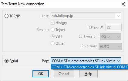
Start Tera Term, select Serial(E), select Port(R):, select the COM port that contains STLink Virtual Com Port, and click OK button.
In our environment, COM3 was assigned to the Virtual Com Port.
The ST system has created a virtual COM port environment, so let's use it.
Next, go to Settings - Serial Port in the menu and set the communication parameters as shown below and press the OK button.
These should match the values set in MX_USART2_UART_Init().

Please connect the microcontroller board to your PC with a USB cable.
Code Summary
The following function sends without DMA. It works in blocking mode.
HAL_UART_Transmit(&huart2, buffer, 10, 1000);
The following function transmits using DMA. It works in non-blocking mode.
HAL_UART_Transmit_DMA(&huart2, buffer, 10);
HAL_GetTick() is a function that reads a counter that counts up every 1msec.
You can find the approximate processing time by putting this function before and after the process and subtracting the return value of each.
The result should be t3 >> t4.
Write the following code in DMA1_Stream6_IRQHandler() to accept the next transmission.
huart2.gState = HAL_UART_STATE_READY;
Let's try to run the program
Now, let's try to run the program with Run - Resume.
If the string "abcdefghij" is displayed and updated in Tera Term in one second cycle, the program is successful.
In this environment, t3 is about 83 and t4 is 0.
Since the baud rate is 1200bps, the transmission time is 1/1200 * 10bit * 10byte = about 83msec.
In the case of HAL_UART_Transmit(), which transmits without using DMA, we can see that the function does not return until the 10 bytes of data are sent.
In comparison, HAL_UART_Transmit_DMA() returns in a much faster time.
Even if you subtract the overhead of interrupt processing, you still get a good chunk of change.
What do you think?
It turns out that DMA can be used for efficient transmission processing.


