
This time, let’s check the PWM output.
I will write down the development environment at the time of posting.
PC: Windows 10 OS
IDE: STM32CubeIDE Version 1.3.0
Configurator: STM32CubeMX Version 5.6.0
Board: STM32 Nucleo-F401RE
What is PWM?
PWM is an abbreviation for Pulse Width Modulation.
It is a function to output a pulse from the GPIO port.
By changing the pulse width, you can control the motor and adjust the brightness of the LED.
This time, the green LED (LD2) on the board happens to be connected to the PWM output port, so let’s use it.
Create a project
Launch the IDE, select File-New –STM32 Project, select the Board Selector tab when the Target Selection window appears, select NUCLEO-F401RE from the Boards List and press the Next button.
Enter F401PWmHAL for the Project name and press the Finish button.
Press Yes when you are asked Initialize all peripherals with their default Mode ?.
This kind of project is associated with the STM32CubeMx perspective. Do you want to open this perspective now? And press Yes.
Set PWM output with code generator
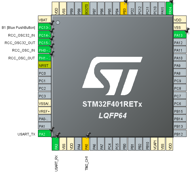
The terminal to be set this time is the lower PA5.
Right click on PA5 and select TIM2_CH1 from the list.
Then select Pinout & Configuration –Category –Timers –TIM2
TIM2 Mode and Configuration –Mode –Select PWM Generation CH1 from the list of Channel1.
TIM2 Mode and Configuration –Configuration –Set Parameter Settings as follows.
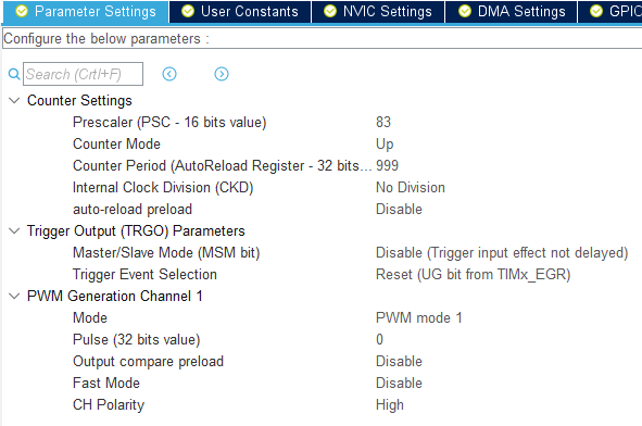
Because HCLK is 84MHz
84MHz / ((83 + 1) * (999 + 1)) = 84 * 10 ^ 6 Hz / (84 * 10 ^ 3) = 10 ^ 3 Hz = 1 kHz
This setting results in a PWM output with a period of 1kHz.
Select F401PWmHAL in Project Explorer and build with Project – Build Project.
Add code
Code the while () loop part of main () as follows.
 / * USER CODE BEGIN WHILE * /
  HAL_TIM_PWM_Start (& hitim2, TIM_CHANNEL_1);
  while (1)
  {
    __HAL_TIM_SET_COMPARE (& hitim2, TIM_CHANNEL_1, 250);
    HAL_Delay (100);
    __HAL_TIM_SET_COMPARE (& hitim2, TIM_CHANNEL_1, 500);
    HAL_Delay (100);
    / * USER CODE END WHILE * /

    / * USER CODE BEGIN 3 * /
  }
  / * USER CODE END 3 * /
Build and run
Build and make sure there are no errors and run the program.
Run –Resume
If the green LED becomes brighter or darker, you are successful.
I observed the waveform with an oscilloscope for confirmation.
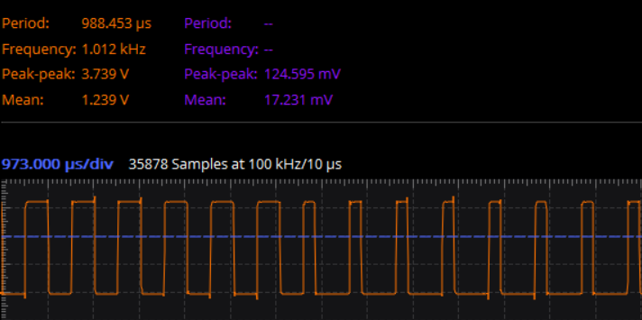
It was confirmed that the frequency was about 1kHz.
Code overview
Start PWM output with HAL_TIM_PWM_Start ().
__HAL_TIM_SET_COMPARE is a macro that changes the value of register CCR.
__HAL_TIM_SET_COMPARE (& hitim2, TIM_CHANNEL_1, 250);
You can change the duty ratio of TIM2 and CH1 with.
CCR is a 32-bit register, but it doesn’t need to be that big.
The value of the third argument is 500 and the duty ratio is 50%. (The left part of the above waveform)
At 250, the H level period is halved. (The right part of the above waveform)
There was the following description in the reference manual.
In pulse width modulation (PWM) mode, the frequency determined by the value of the TIMx_ARR register and TIMx_CCRx
The signal can be generated with a duty cycle determined by the register value.
Counter Period (== 999) on the setting screen is the value of TIM2_ARR.
The denominator is 1000 because the up counter is designed so that the first count is 0.
Since the PWM output signal is connected to the anode of the LED, if the value of the third argument of __HAL_TIM_SET_COMPARE () is n
The LED will be lit for n / 1000 periods. (N is the value of TIM2_CCRx)
How was it, did you all succeed in PWM output?


