
This time I will talk about RTC.
I will write down the development environment at the time of posting.
PC: Windows 10 OS
IDE: STM32CubeIDE Version 1.3.0
Configurator: STM32CubeMX Version 5.6.0
Board: STM32 Nucleo-F401RE
What is RTC?
RTC is an abbreviation for Real Time Clock and is a function of the clock.
Connect the batteries
Since it’s a big deal, I’ll try connecting the batteries and check the operation when the power is turned off.
However, the circuit is simple.
The circuit this time is an experimental one that drains the battery regardless of whether the power is on or off.
To make it practical, you need a circuit that switches between normal power and battery power to supply VBAT.
Prepare a battery with a nominal 3V system, a battery holder attached, and a wire drawn out.
I also want to check the processing when the power is turned off, so remove the SB45 in the figure below.
The SB45 has a 0Ω resistor, so remove it.
Please save it so that you do not lose it.
With a C29 1uF capacitor, this will back up VBAT for a short time, even without batteries.
If you want to create a clear VBAT = 0V state, you can remove C29.
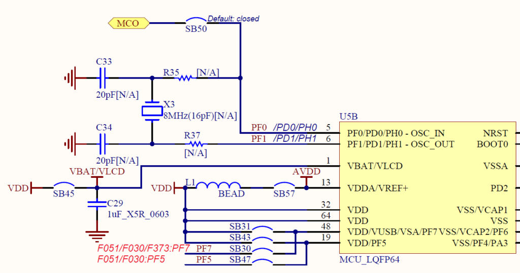
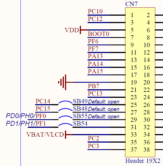
Then connect the + terminal of the battery to VBAT / VLCD and the-terminal of the battery to GND.
Here, I connected the + terminal of the battery to the 33rd pin of CN7, and connected the-terminal of the battery to the 19th pin of CN7.
Create a project
Launch the IDE, select File-New –STM32 Project, select the Board Selector tab when the Target Selection window appears, select NUCLEO-F401RE from the Boards List and press the Next button.
Enter F401RTcHAL for the Project name and press the Finish button.
Press Yes when you are asked Initialize all peripherals with their default Mode ?.
This kind of project is associated with the STM32CubeMx perspective. Do you want to open this perspective now ?, so press Yes.
Set RTC with code generator
Select Pinout & Configuration –Category –Timers –RTC and
Check Activate Clock Source for Mode in RTC Mode and Configuration.
Clock Configuration –Select LSE in the RTC Clock Mux.
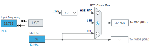
Let me explain why you choose LSE.
This is because the LSE operates if the VBAT has a voltage higher than the specified voltage even when the power is turned off, so the RTC can be clocked even when the power is turned off.
If you do not select LSE, even if you can back up with VBAT, the RTC cannot time while the power is off, and the time in between will stop.
Of course, you need to connect a crystal to OSC32_IN (OSC32_OUT).
(Crystal is mounted on the STM32 Nucleo-F401RE board)
Select F401RTcHAL in Project Explorer and build it with Project – Build Project.
Coding
Write the following code just before main ().
This is the debugging code to check the RTC time in real time.
For this printf () debugging, please refer to the here article for the settings.
 / * USER CODE BEGIN 0 * /
#include & lt; stdio.h & gt;
int __io_putchar (uint8_t ch)
{
  return ITM_SendChar (ch);
}
/ * USER CODE END 0 * /
Write the following code near the while () loop.
 / * USER CODE BEGIN WHILE * /
RTC_TimeTypeDef sTime;
RTC_DateTypeDef sDate;
while (1)
{
  HAL_RTC_GetTime (& hrtc, & sTime, RTC_FORMAT_BIN);
  HAL_RTC_GetDate (& hrtc, & sDate, RTC_FORMAT_BIN);
  printf ("20% 02d.% 02d.% 02d% 02d:% 02d:% 02d \ r \ n", sDate.Year, sDate.Month, sDate.Date, sTime.Hours, sTime.Minutes, sTime.Seconds) ;
  HAL_Delay (1000);
  / * USER CODE END WHILE * /
  / * USER CODE BEGIN 3 * /
}
/ * USER CODE END 3 * /
Rewrite MX_RTC_Init () output by the code generator as follows.
 static void MX_RTC_Init (void)
{

  / * USER CODE BEGIN RTC_Init 0 * /
  / * USER CODE END RTC_Init 0 * /

  / * USER CODE BEGIN RTC_Init 1 * /
  / * USER CODE END RTC_Init 1 * /
  / ** Initialize RTC Only
  * /
  hrtc.Instance = RTC;
  hrtc.Init.HourFormat = RTC_HOURFORMAT_24;
  hrtc.Init.AsynchPrediv = 127;
  hrtc.Init.SynchPrediv = 255;
  hrtc.Init.OutPut = RTC_OUTPUT_DISABLE;
  hrtc.Init.OutPutPolarity = RTC_OUTPUT_POLARITY_HIGH;
  hrtc.Init.OutPutType = RTC_OUTPUT_TYPE_OPENDRAIN;
  if (HAL_RTC_Init (& hrtc)! = HAL_OK)
  {
    Error_Handler ();
  }
  / * USER CODE BEGIN RTC_Init 2 * /

#define MAGIC_NO 0x12a5

  if (HAL_RTCEx_BKUPRead (& hrtc, RTC_BKP_DR0)! = MAGIC_NO)
  {
    RTC_TimeTypeDef sTime = {0};
    RTC_DateTypeDef sDate = {0};

    sTime.Hours = 1;
    sTime.Minutes = 0;
    sTime.Seconds = 0;
    if (HAL_RTC_SetTime (& hrtc, & sTime, RTC_FORMAT_BIN)! = HAL_OK)
    {
      Error_Handler ();
    }
    sDate.WeekDay = RTC_WEEKDAY_WEDNESDAY;
    sDate.Month = RTC_MONTH_JANUARY;
    sDate.Date = 1;
    sDate.Year = 20;
    if (HAL_RTC_SetDate (& hrtc, & sDate, RTC_FORMAT_BIN)! = HAL_OK)
    {
      Error_Handler ();

    }
    HAL_RTCEx_BKUPWrite (& hrtc, RTC_BKP_DR0, MAGIC_NO);
  }
  / * USER CODE END RTC_Init 2 * /
}
Build and run
Run –Resume.
Once the program has stopped before execution, press the 〇 part of the SWV ITM Data Console to enable printf () output.
![]()
Then run.
Only at the very beginning, the timekeeping starts at 2020.01.01 01:00:00.
While backing up with batteries, the RTC will keep time even when the power is off.
Code overview
Inside MX_RTC_Init ()
After HAL_RTC_Init (), read the contents of the backup register with HAL_RTCEx_BKUPRead (& hrtc, RTC_BKP_DR0).
If the value of the backup register is correct, no further processing is performed.
The value (MAGIC_NO) written in the backup register is meaningless and was decided appropriately.
If the read value is incorrect, it is determined that the power could not be supplied to VBAT and the date and time are initialized.
In this sample, it is set to 2020.01.01 01:00:00.
The first two digits of the Christian era are omitted and fixed at 20.
Since there are multiple backup registers, there is also a way to save this value and read it.
After that, the while () loop reads the time every second and outputs printf ().
How was it? Did you keep time?


