
In this article, we will try to access the memory (EEPROM) using HAL’s I2C.
I have previously written an article on barometric pressure sensors using I2C, but EEPROM may be more practical.
The following is the development environment at the time of submission.
PC: Windows 10 OS
IDE: STM32CubeIDE Version1.3.0
Configurator: STM32CubeMX Version5.6.0
Board: STM32Nucleo-F401RE
Overview of I2C communication
A communication method developed by Philips (now NXP) Semiconductors.
Two communication lines, SCL and SDA, for bi-directional communication
There are several options for communication speed, such as 100k, 1Mbits/sec, etc.
There are master and slave devices, and a multi-master system is possible.
For more information about I2C, please refer to here.
Target to be a slave
I used the STM32 as the master and Microchip’s 24LC256 as the slave device memory.
EEPROM stands for Electrically Erased PROM, which is an electrically erasable non-volatile memory.
It can be used for applications where you want to store setting values.
For the datasheet, please see DataSheet 24LC256 for the datasheet.
This is somewhat of a ramble, but
The 24 part represents the I2C interface.
The 25 represents SPI.
The LC part seems to be the voltage used or the communication speed.
LC is 2.5 to 5.5V, so it can be used at 3.3V.
256 is the size, representing 256Kbit (32K x 8bit).
The pin numbers are as follows
1: A0
2: A1
3:A2
Pins 1 to 3 are for addressing.
This allows you to connect up to 8 devices to a single I2C bus.
Since we will be connecting only one device, we will connect all of them to GND.
4: GND
GND pin.
5:SDA
Connect the SDA of the microcontroller.
6:SCL
Connects to SCL of the microcontroller.
7:WP
High active write protect.
Connect to GND since writing is not possible when protected.
8:VCC
Connect 3.3V.
Connection
Connect as shown in the table below.
The SDA and SCL signals should be pulled up to 3.3V.
In this case, I used 10kΩ to pull them up.

Create a project
Start the IDE, select File- New – STM32 Project, when the Target Selection window comes up, select the Board Selector tab, select NUCLEO-F401RE from the Boards List and press the Next button.
Enter F401I2cHAlMem as the Project name and press the Finish button.
It will ask “Initialize all peripherals with their default Mode ? Press Yes.
This kind of project is associated with the STM32CubeMx perspective. Do you want to open this perspective now ? Press Yes.
Adding the I2C interface in the code generator
The I2C pins we will use are PB8 and PB9. (The area circled in red near the top left of the image)
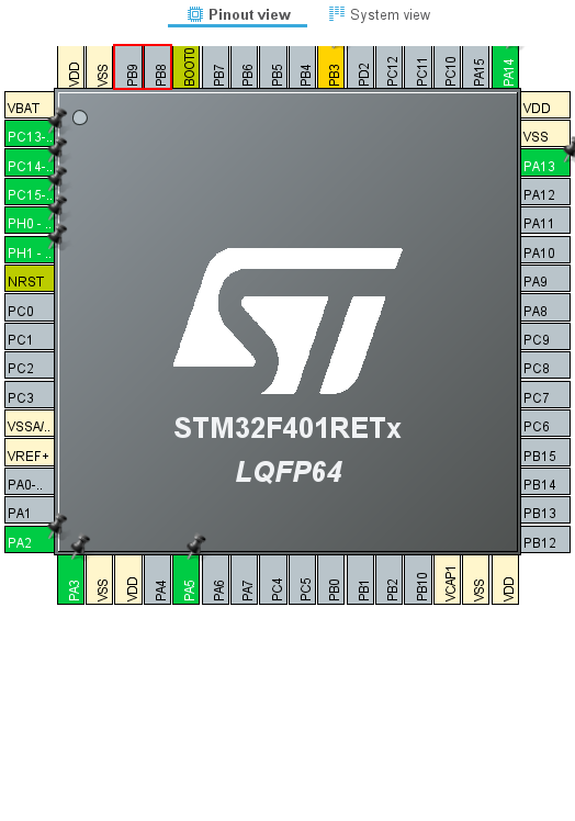
Right-click on PB8 to select it, then select I2C1_SCL.
Right-click on PB9 to select it, and then select I2C1_SDA.
Make sure that the color of the pin changes from gray to yellow.
Then select Pinout & Configuration – Categories – Connectivity – I2C1
Select I2C from the list of I2C in I2C1 Mode and Configuration – Mode.
Select F401I2cHAlMem in the Project Explorer and build it in Project – Build Project.
The color of the pins will change from yellow to green.
Also, make sure that MX_I2C1_Init() is generated in main.c.
How to access
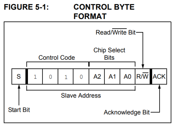
Let’s look at the first control byte to be specified.
In the case of this device, the upper 4 bits will be in the pattern 1010.
A2-A0 will be connected to GND, so the pattern will be 000.
The address in the bare state is 0x50, but as you know, I2C uses the address shifted one bit to the left.
As you know, I2C uses the address shifted one bit to the left, so 0xa0 is used, and the least significant bit is set to 1 for read and 0 for write.
However, you don’t need to be aware of this in your program, since the HAL function takes care of setting 1 when reading.
The control byte is written in hexadecimal notation as follows
When read: 0xa1
When writing: 0xa0
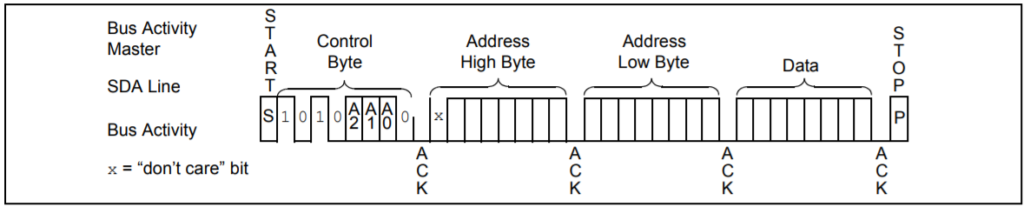
Byte Write
The format for writing in bytes is as follows.
Since this device is 32 KByte, the most significant bit of the 16-bit address is Don’t cate because it has no meaning.
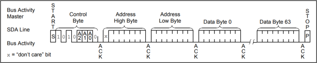
Page Write
The format for writing in pages is as follows.
One page is 64 bytes.
Random Reads
The format for a random read is as follows
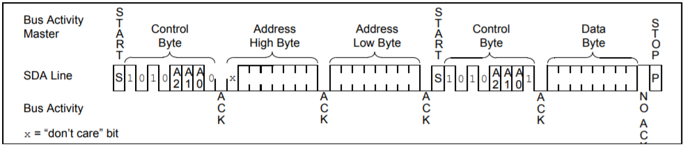
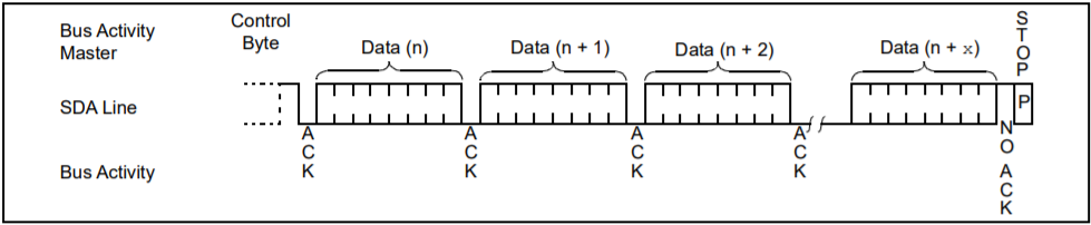
Sequential Read
The format for sequential reads is as follows
Add the code
I wrote the code to be completed within the MX_I2C1_Init() function.
static void MX_I2C1_Init(void)
{
  /* USER CODE BEGIN I2C1_Init 0 */ /* USER CODE END I2C1_Init
  /* USER CODE END I2C1_Init 0 */ /* USER CODE BEGIN I2C1_Init 0
  /* USER CODE BEGIN I2C1_Init 1 */ /* USER CODE END I2C1_Init 0
  /* USER CODE END I2C1_Init 1 */ /* USER CODE
  Instance = I2C1;
  Init.ClockSpeed = 100000;
  Init.DutyCycle = I2C_DUTYCYCLE_2;
  Init.OwnAddress1 = 0;
  Init.AddressingMode = I2C_ADDRESSINGMODE_7BIT;
  Init.DualAddressMode = I2C_DUALADDRESS_DISABLE;
  Init.OwnAddress2 = 0;
  Init.GeneralCallMode = I2C_GENERALCALL_DISABLE;
  Init.NoStretchMode = I2C_NOSTRETCH_DISABLE;
  if (HAL_I2C_Init(&hi2c1) ! = HAL_OK)
  {
    Error_Handler();
  }
  /* USER CODE BEGIN I2C1_Init 2 */

  uint8_t sbuf[128] = {0}
  uint8_t rbuf[128] = {0};
  HAL_StatusTypeDef s;

#define DEVICE_ADDR 0xa0
#define BYTES_PER_PAGE 64

  for (int i = 0; i < BYTES_PER_PAGE; i++)
  {
	  sbuf[i] = i;
  }
  s = HAL_I2C_Mem_Write(&hi2c1, DEVICE_ADDR, 0, I2C_MEMADD_SIZE_16BIT, sbuf, BYTES_PER_PAGE, 1000);
  s = HAL_I2C_Mem_Read(&hi2c1, DEVICE_ADDR, 0, I2C_MEMADD_SIZE_16BIT, rbuf, BYTES_PER_PAGE, 1000);

  /* USER CODE END I2C1_Init 2 */ .
}
Explanation of the code
There seems to be a dedicated API for Memory read/write, so I used it.
They are HAL_I2C_Mem_Write() and HAL_I2C_Mem_Read().
First argument: instance (pointer to a structure)
2nd argument: I2C device address (value with one bit shifted to the left)
3rd argument: Memory address
4th argument: Size of the memory address
5th argument: Buffer to be read or written
6th argument: Number of bytes to be read or written
Argument 7: Timeout value [msec].
It can't be helped that the HAL manual is in English, but I would like to see more detailed information about the parameters.
For example, I couldn't figure out what to set for the fourth argument.
For the fourth argument, I specified I2C_MEMADD_SIZE_16BIT.
You may not know how many to set here just by reading the manual.
I was able to figure it out by looking inside the HAL API functions.
In the above format, the address is 2 bytes (16 bits), so in that case, specify I2C_MEMADD_SIZE_16BIT.
In the case of 24LC01 or 24LC02, the address is only 1 byte (8 bits) because the capacity is small.
In this case, specify I2C_MEMADD_SIZE_8BIT.
In this case, specify I2C_MEMADD_SIZE_8BIT. However, nowadays, there is no need to choose a device with low capacity.
You can buy a 24LC256 for about 100 yen.
Another point to note is that the sixth byte argument BYTES_PER_PAGE should not exceed 64.
If it exceeds 64, the buffer specified for reading will be overwritten from the beginning.
(In the case of this memory, the number of bytes in a page is 64.
Write 0 to 63 for memory addresses 0 to 63, and then read them again.
If the written values are read correctly in the receive buffer, it is a success.
I was able to use it without being aware of random or sequential.
In the case of I2C memory, it can be read and written with a single function, so I guess it is easy to handle.
This time it took a bit of time because of the wiring work.
Did you find it easy to read and write in your environment?


