
In this article, I will use FreeRTOS signal events.
Here is the development environment at the time of submission.
PC: Windows 10 OS
IDE: STM32CubeIDE Version1.3.0
Configurator: STM32CubeMX Version5.6.0
Board: STM32Nucleo-F401RE
In FreeRTOS, one of the task notifications is an event flag, which in FreeRTOS is called a signal event.
In this example, we will use inter-task communication to tell other threads when a switch is pressed.
On the receiving side, we will try to make the LED blink.
Create an IDE project
Select File – New -STM32 Project, select NUCLEO-F401RE from the Boart Selector tab, and press the Next button.
The Project Name should be RtosSignal.
The language should be C, so press Finish.
When it asks “Initialize all peripherals with their default Mode?”, press Yes.
This kinod of project is associated with the STM32CubeMx perspectiove.
Press Yes when it asks “Do you want to open this perspective now?
Add FreeRTOS
Check Middleware – FREERTOS in Pinout & Configuration – Categories.
Select CMSIS_V1 from Mode , Interface under FREERTOS Mode and Configuration on the right.
This is the version of the OS.
Either one is fine, but we’ll use the stable V1 one.
Modify the SysTick
Next, go to Pinout & Configuration – Categories, System Core, SYS – Timebase Source and select TIM5.
This is because FreeRTOS recommends that you use a Timebase Source other than SysTick.
Add a task
Under FreeRTOS Mode, in Configuration, select Tasks & Queues.
Press the Add button, the one above the one for Tasks.
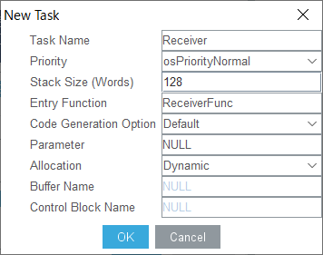
Change only the following three items in the list as shown below, and press the OK button.
Task Name : Receiver
Priority : osPriorityNormal
Entry Function : ReceiveFunc
You can think of tasks here as meaning the same as threads.
The term “thread” will be used throughout the rest of this article.
Configuring GPIOs
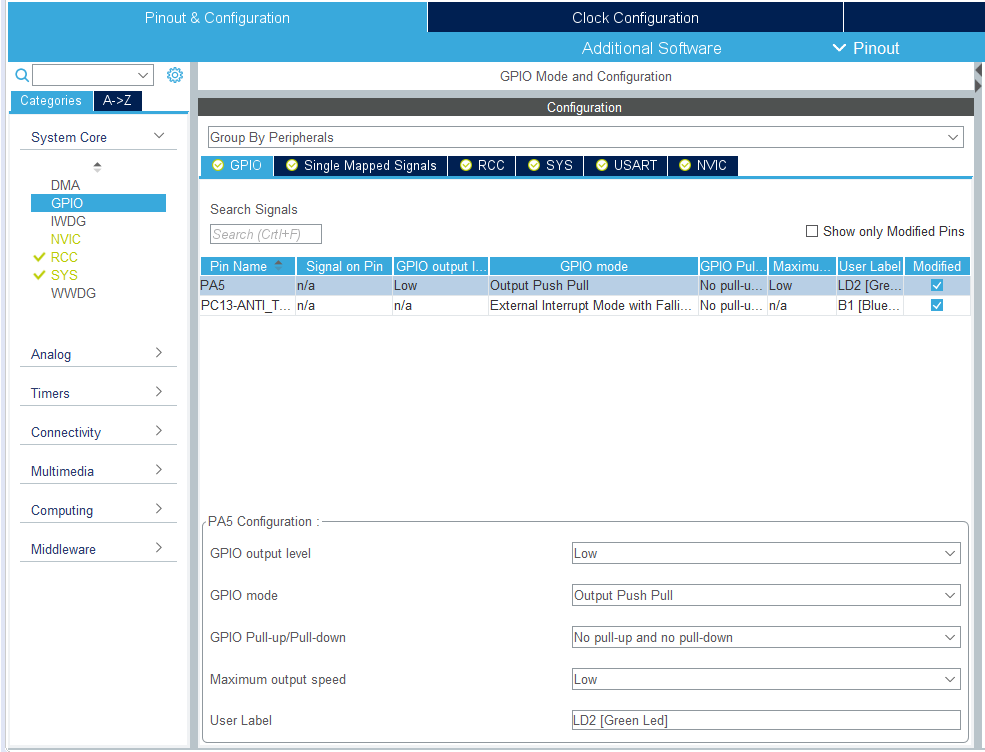
Select GPIO from Pinout & Configuration – Categories – System Core.
With the GPIO tab selected, select PA5 for Pin Name.
Make sure that GPIO mode is set to Output Push Pull.
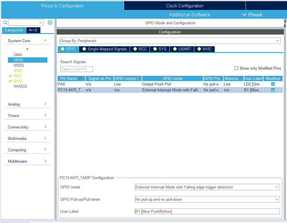
Next, select the Pin Name PC13-ANTI_TAMP.
Make sure that GPIO mode is set to External Interruput Mode with Falling edge trigger detection.
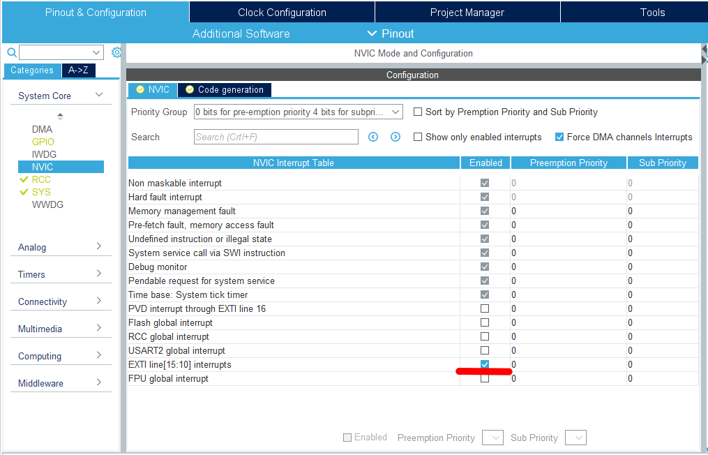
Next, select NVIC from Pinout & Configuration – Categories – System Core.
Check the Enabled box for EXTI line[15:10] interrupts to allow interrupts.
Implementation of Signal Events
For more information about signal events, please refer to here.
Coding
Write the following code before main().
/* USER CODE BEGIN 0 */.

#define FLGPTN 0x00000001

void HAL_GPIO_EXTI_Callback(uint16_t GPIO_Pin)
{
  if (GPIO_Pin == GPIO_PIN_13)
  {
    osSignalSet(ReceiverHandle, FLGPTN);
  }
}
/* USER CODE END 0 */
Write the following code in ReceiveFunc().
void ReceiveFunc(void const * argument)
{
  /* USER CODE BEGIN ReceiveFunc */
  /* Infinite loop */
  for(;;)
  {
	  for(;;;)
	  {
	    osEvent event = osSignalWait(FLGPTN, osWaitForever);
	    if (event.status == osEventSignal && event.value.signals == FLGPTN)
	    {
	    	HAL_GPIO_TogglePin(GPIOA, GPIO_PIN_5);
	    }
	  }
      osDelay(1);
  }
  /* USER CODE END ReceiveFunc */
}
Code summary
osSignalSet()
First argument: Value of the osThreadId type obtained by osThreadCreate()
Second argument: Signal flag
osSignalWait()
1st argument: Signal flag
Second argument: Timeout value (milliseconds) or infinite wait (osWaitForever)
The signal event is set with osSignalSet(), and
Set the signal event with osSignalSet() and wait with osSignalWait().
After exiting from osSignalWait(), check the flags with if() before processing.
It is a success if LD2 (green) blinks every time the switch is pressed.
We used an interrupt to detect switch presses.
If you want to know more about GPIO interrupts, please refer to the article Using Interrupts with HAL GPIOs.
How was it, everyone? Did you get the LED-blink ?


