
Hello everyone.
This time, I’ll try to output the GPIO initialization code for each HAL and LL in the IDE.
Here is the development environment at the time of posting.
(I have upgraded the development environment of CubeIDE and CubeMX as follows)
PC: Windows 10 OS
IDE: STM32CubeIDE Version1.5.0
Configurator: STM32CubeMX Version6.1.0
Board: STM32Nucleo-F401RE
Starting with the HAL project
The default initialization code in the IDE is HAL, which we haven’t noticed before.
To review, let’s generate a project for the above board.
Start the IDE, select File- New – STM32 Project, when the Target Selection window comes up, select the Board Selector tab, select NUCLEO-F401RE from the Boards List and press the Next button. Click the Next button.
Enter F401GpioHAL as the Project name and press the Finish button.
It will ask “Initialize all peripherals with their default Mode ? and press Yes.
Build it
Select Project – Build All.
The Console will show that there are no errors.
07:12:16 Build Finished. 0 errors, 0 warnings. (took 3s.145ms)
Connect the board to the PC and enter debug mode
Connect the board to the PC with a USB cable.
In the Project Explorer, click on F401GpioHAL to select it, and then select Run – Debug.
This kind of launch is configured to open tihe Debug perspective when it suspends.
This Debug perspective supports application debugging by providing views for displaying the debug stack, variables and breakpoints.
This kind of launch is configured to open tihe Debug perspective when it suspends.
(Do you want to switch to this perspective now?).
(Do you want to switch to this perspective now?). Check the Remember my decision checkbox and press the switch button.
Check ROM and RAM usage (HAL)
Select Window – Show View – Build Analyzer.
The Memory Regions tab is selected and you can see the RAM and ROM usage.
RAM Used 1.61KB
ROM Used 7.9KB
You can see the percentage of RAM and ROM used.
This is useful because you can see what percentage of the data has been used.
You can also refer to Build Analyzer related articles.
Looking at main.c, the initialization code for GPIO using HAL is as follows.
static void MX_GPIO_Init(void)
{
  GPIO_InitTypeDef GPIO_InitStruct = {0}

  /* GPIO Ports Clock Enable */
  __HAL_RCC_GPIOC_CLK_ENABLE();
  __HAL_RCC_GPIOH_CLK_ENABLE();
  __HAL_RCC_GPIOA_CLK_ENABLE();
  __HAL_RCC_GPIOB_CLK_ENABLE();

  /*Configure GPIO pin Output Level */
  HAL_GPIO_WritePin(LD2_GPIO_Port, LD2_Pin, GPIO_PIN_RESET);

  /*Configure GPIO pin : B1_Pin */
  GPIO_InitStruct.Pin = B1_Pin;
  GPIO_InitStruct.Mode = GPIO_MODE_IT_FALLING;
  GPIO_InitStruct.Pull = GPIO_NOPULL;
  HAL_GPIO_Init(B1_GPIO_Port, &GPIO_InitStruct);

  /*Configure GPIO pin : LD2_Pin */
  GPIO_InitStruct.Pin = LD2_Pin;
  GPIO_InitStruct.Mode = GPIO_MODE_OUTPUT_PP;
  GPIO_InitStruct.Pull = GPIO_NOPULL;
  GPIO_InitStruct.Speed = GPIO_SPEED_FREQ_LOW;
  HAL_GPIO_Init(LD2_GPIO_Port, &GPIO_InitStruct);

}
GPIO initialization code quantity (for HAL)
In the Build Analyzer, I selected Memory Detailes and went down the tree FLASH – .text and found MX_GPIO_Init.
Size is 224B (Byte).
It’s useful to know how much ROM is consumed per function.
Let’s try to create a project to initialize GPIOs in LL
Now let’s move on to LL.
If the previous project is still running, select Run – Terminate (or the red square button) to stop it.
Leave the project as it is and create another project for LL.
Start the IDE, select File- New – STM32 Project, when the Target Selection window comes up, select the Board Selector tab, select NUCLEO-F401RE from the Boards List and press Next. Click the Next button.
Enter F401GpioLL as the Project Name and press the Finish button.
It will ask “Initialize all peripherals with their default Mode ? Press the Yes button.
Configure to use LL for GPIO initialization
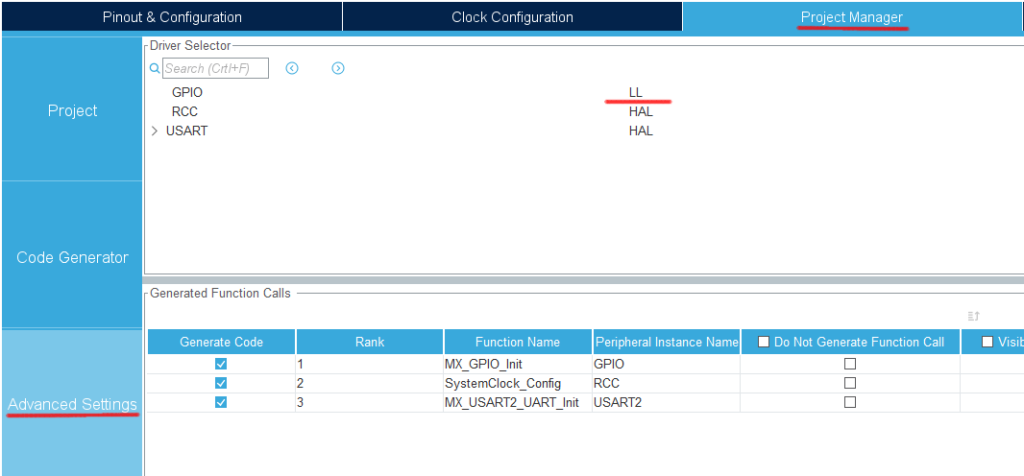
Select the Project Manager tab and change the GPIO in Advanced Settings from HAL (default) to LL. (Select it in the combo box)
Select Project – Build All.
When it asks “Do you want Generate Code ? Check the Remember my decision checkbox and press OK.
This action can be associated with C/C++ perspective.
This action can be associated with C/C++ perspective.
Select F401GpioLL in the Project Explorer and select Run – Debug.
When the Edit Configuration window comes up, press OK.
Check ROM and RAM usage (LL)
In the bottom pane of the screen, select the Build Analyzer that you just saw.
Select the Memory Regions tab to see the RAM and ROM usage.
RAM Used 1.61KB
ROM Used 9.43KB
A lot more code area is used than in HAL.
Looking at main.c, the initialization code for GPIO using LL is as follows.
static void MX_GPIO_Init(void)
{
  LL_EXTI_InitTypeDef EXTI_InitStruct = {0}
  LL_GPIO_InitTypeDef GPIO_InitStruct = {0}

  /* GPIO Ports Clock Enable */ LL_AHB1_GRP
  LL_AHB1_GRP1_EnableClock(LL_AHB1_GRP1_PERIPH_GPIOC);
  LL_AHB1_GRP1_EnableClock(LL_AHB1_GRP1_PERIPH_GPIOH);
  LL_AHB1_GRP1_EnableClock(LL_AHB1_GRP1_PERIPH_GPIOA);
  LL_AHB1_GRP1_EnableClock(LL_AHB1_GRP1_PERIPH_GPIOB);

  /**/
  LL_GPIO_ResetOutputPin(LD2_GPIO_Port, LD2_Pin);

  /**/
  LL_SYSCFG_SetEXTISource(LL_SYSCFG_EXTI_PORTC, LL_SYSCFG_EXTI_LINE13);

  /**/
  EXTI_InitStruct.Line_0_31 = LL_EXTI_LINE_13;
  EXTI_InitStruct.LineCommand = ENABLE;
  EXTI_InitStruct.Mode = LL_EXTI_MODE_IT;
  EXTI_InitStruct.Trigger = LL_EXTI_TRIGGER_FALLING;
  LL_EXTI_Init(&EXTI_InitStruct);

  /**/
  LL_GPIO_SetPinPull(B1_GPIO_Port, B1_Pin, LL_GPIO_PULL_NO);

  /**/
  LL_GPIO_SetPinMode(B1_GPIO_Port, B1_Pin, LL_GPIO_MODE_INPUT);

  /**/
  GPIO_InitStruct.Pin = LD2_Pin;
  GPIO_InitStruct.Mode = LL_GPIO_MODE_OUTPUT;
  GPIO_InitStruct.Speed = LL_GPIO_SPEED_FREQ_LOW;
  GPIO_InitStruct.OutputType = LL_GPIO_OUTPUT_PUSHPULL;
  GPIO_InitStruct.Pull = LL_GPIO_PULL_NO;
  LL_GPIO_Init(LD2_GPIO_Port, &GPIO_InitStruct);

}
At a glance, it looks like there is more code than in the HAL case.
There may be a difference in the amount of code used for the part that processes rather than initializes.
Files added by the configurator
In Project EXplorer
Drivers\STM32F4xx_HAL_Driver\Src
Drivers\STM32F4xx_HAL_Driver\Inc
in the Project EXplorer, you will see that by default, only the HAL drivers are present, but if you select LL, the LL drivers will be included.
If you look at the functions in this section, you may learn something.
In the case of GPIO output, you can write
Write 0
Write 1
Invert the output
In the case of GPIO output, the functions are – Write 0 – Write 1 – Invert the output, so it is good to compare them.
Here, we will compare only the function to invert the output.
In HAL (stm32f4xx_hal_gpio.c)
void HAL_GPIO_TogglePin(GPIO_TypeDef* GPIOx, uint16_t GPIO_Pin)
{
  /* Check the parameters */
  assert_param(IS_GPIO_PIN(GPIO_Pin));

  if ((GPIOx->ODR & GPIO_Pin) == GPIO_Pin)
  {
    GPIOx->BSRR = (uint32_t)GPIO_Pin << GPIO_NUMBER;
  }
  } else
  {
    GPIOx->BSRR = GPIO_Pin;
  }
}
In LL (stm32f4xx_ll_gpio.h)
__STATIC_INLINE void LL_GPIO_TogglePin(GPIO_TypeDef *GPIOx, uint32_t PinMask)
{
  WRITE_REG(GPIOx->ODR, READ_REG(GPIOx->ODR) ^ PinMask);
}
The feature of LL is that it is an inline function.
(Inline functions are written in the header file.)
(Inline functions are written in the header file.) It looks like a function, but in LL, it is often inline.
Inline functions are written in a very compact way.
Looking at this code, LL is by far the faster of the two.
Even if HAL doesn’t have the if() function.
If speed is a priority, LL should be used, taking into account the overhead of function calls.
Inline functions are not subroutine calls, but embed code in place, thus saving time on stack operations.
(In-line functions are not subroutine calls.
(Note: Depending on the compiler’s optimization options, the embedding or subroutine call will be different.
We have been looking at GPIOs as an example.
We need to reduce the amount of code.
In situations where the execution speed must be increased
In such a situation, I think LL is worth a try.
However, you need to read the register manual carefully.
There are some drawbacks in using LL, such as the difficulty in understanding how to use the functions (there are few documents).
There seems to be many difficulties in handling it.
Well, that’s it for this time.
Thank you for your time.


