
Hello everyone.
I’m going to start using LL to communicate via UART.
The following is the development environment at the time of submission.
PC: Windows 10 OS
IDE: STM32CubeIDE Version1.5.0
Configurator: STM32CubeMX Version6.1.0
Board: STM32Nucleo-F401RE
Create a project
Start the IDE, select File- New – STM32 Project, when the Target Selection window comes up, select the Board Selector tab, select NUCLEO-F401RE from the Boards List and press the Next button. Click the Next button.
Enter F401UartLL as the Project name and press the Finish button.
It will ask “Initialize all peripherals with their default Mode ? Press Yes.
Getting ready to use the UART with LL
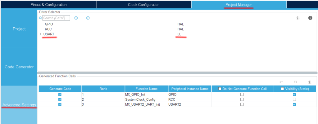
Select the Project Manager tab and change the USART in Advanced Settings from HAL (default) to LL. (Use the combo box to select)
Click on the HAL section to display the combo box list, and select LL.
Select Project – Build All.
When it asks “Do you want Generate Code ? Check the Remember my decision checkbox and press OK.
This action can be associated with C/C++ perspective.
This action can be associated with C/C++ perspective.
Check the LL initialization code
In main.c, there is a function called MX_USART2_UART_Init().
If you look inside it, you can see that the function starts with LL_ instead of HAL_.
Modify the UART parameters
Double-click F401UartLL.ioc from the Project Explorer to open the GUI window.
Select Pinout & Configuration – Connectivity – USART2.
In the Mode section, Asynchronus is selected and ready to use. (Disable if you don’t want to use it.)
Let’s try using parity this time.
In the Configuration – Parameter Settings section, set as follows.
(The only change from the default is to change Parity from None to Even)
Baud Rate : 115200
Word Length : 8bits
Parity : Even
Stop Bits : 1
Configure the interrupt settings while you’re at it
Check the Enabled checkbox for USART2 global interrupt in Configuration – NVIC Settings.
Now let’s build and check the code once.
Select Project – Build All.
The following code is a part of the MX_USART2_UART_Init() function.
 NVIC_SetPriority(USART2_IRQn, NVIC_EncodePriority(NVIC_GetPriorityGrouping(),0, 0));
  NVIC_EnableIRQ(USART2_IRQn);
.
.
.
  USART_InitStruct.BaudRate = 115200;
  USART_InitStruct.DataWidth = LL_USART_DATAWIDTH_8B;
  USART_InitStruct.StopBits = LL_USART_STOPBITS_1;
  USART_InitStruct.Parity = LL_USART_PARITY_EVEN;
NVIC_SetPriority(): This function sets the priority of the interrupt.
NVIC_EnableIRQ(USART2_IRQn) : This function enables interrupt for USART2.
These two functions are added by enabling the interrupt.
After that, the communication parameters are set.
BaudRate : This is the communication speed. The unit is bps (b/s), which is bits per second, so it is the number of bits per second.
DataWidth : Data length.
StopBits : Stop bits.
Parity : Parity bits. Set LL_USART_PARITY_NON, ODD or EVEN.
Since we want to use LL for fine control, we decided to use parity as well.
The meaning of each is as follows
NON : None
ODD : Odd
EVEN : even number
One thing to note here is that in the case of STM32, this data length also includes the Parity bit (1 bit).
In the case of the STM32, this data length includes the parity bit (1 bit).
Therefore, the setting on the other side (PC in this case) is as follows (note that the data length is 7).
Communication speed: 115200
Data length: 7
Parity: even
Stop bit: 1 bit
(The communication specification is 7 bits of data and even parity, but you need to set 8 bits of data and even parity on the STM32 microcontroller side to match the specification.)
That’s it for this time.
Thank you for your time.


