
Hello everyone.
In this article, we will try to send communication by UART using LL with polling.
What is LL? If you are wondering what LL is, please refer to the article HAL and LL.
The following is the development environment at the time of posting.
PC: Windows 10 OS
IDE: STM32CubeIDE Version1.5.0
Configurator: STM32CubeMX Version6.1.0
Board: STM32Nucleo-F401RE
Sending by polling
I’m not sure if polling is the right word for sending, but it’s a way to send data in succession while checking if it’s OK to send the next data.
In order to use LL in the future, you need to understand the registers of the peripherals.
For this purpose, please download the reference manual RM0368 for the microcontroller used in this board from here. We will be running the UART.
Since we will be running the UART, please read the USART section in section 19 carefully.
The S in USART stands for Synchronous, and USART is a peripheral that can perform synchronous and asynchronous serial communication.
You can think of the UART as being part of the USART.
For more information on setting up the IDE to use UART with LL, please refer to the article Try UART with STM32 LL Initial setting.
USART registers explained
First of all, please read the control registers 1 (CR1) and 2 (CR2) carefully.
Let’s look at control register 1 first.

Here is an explanation to the best of my understanding.
Bit 15 : Oversampling mode
Set to 0, 16x sampling is fine.
I won’t go into detail, but since this is asynchronous communication without a clock, this is the number of clocks per bit width that the receiver will start sampling after detecting the start bit.
The data is sampled with the clock around half of this number (near the center of each bit).
Bit 13 : USART Enable
Must be set to 1 to use USART.
When the initialization is complete, add a code to set this bit to 1 if it is 0.
Bit 12 : M Word Length
Since we are using 7 bits of data plus parity, this setting is 0.
Bit 11 : Wakeup method
Since we won’t use it, leave it as default (at reset) 0
Bit 10 : PCE Parity Control Enabled
Probably an abbreviation for Parity Check Enabled.
Since parity is used in this case, 1
Bit 9 : PS Parity Select
Probably stands for Parity Select.
Since it is an even parity, it is 0.
Bit 8 : PEIE Parity Error Interrupt Enabled
Probably stands for Parity Error Interrupt Enabled.
Since we think it is not necessary to use it, 0
Bit 7 : TXEIE Transmit Empty Interrupt Enabled
Probably stands for Tx Empty Interrupt Enabled.
Since we don’t need to use it right now, 0 for now.
Set this to 1 if you want to use interrupts for transmission.
Bit 6 : TCIE Transmit Complete Interrupt Enabled
Probably an abbreviation for Transmit Complete Interrupt Enabled.
Since it is not used, set to 0.
Bit 5 : RXNEIE
Probably an abbreviation for Rx Not Empty Interrupt Enabled.
Since it is not used right now, it is 0 for now.
Bit 4 : IDLEIE IDLE Interrupt Enabled
0 since it is not used.
Bit 3 : TE Transmitter Enabled
Probably stands for Transmitter Enabled.
Of course, 1 since it transmits.
Bit 2 : RE Receiver Enabled
1 since we will use it later
Bit 1 : RWU Receiver Wakeup
0 since it is not used.
Bit 0 : SBK Break send
0, not used
Next, control register 2
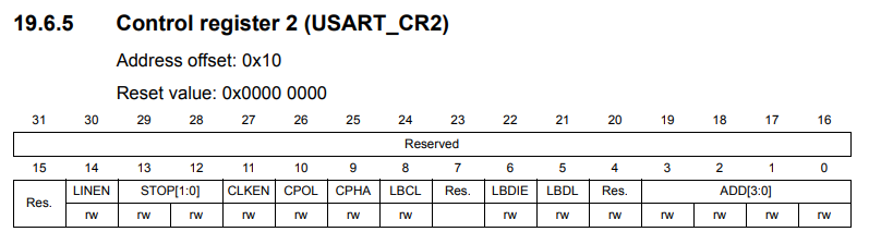
In Control Register 2, the part to understand this time is the stop bit.
Bits 12 and 13 are where the stop bits are set, and since the stop bit is 1 this time, we only need to set 0 to each of them.
However, the configurator has already created the initialization code, so you don’t need to set them.
The other bits are probably functions used in synchronous mode.
Since they are not used in the UART (asynchronous), the default value of 0 for each bit is fine.
To summarize, when the initial settings are done
Control Register 1 (CR1) is 0x240c
Control Register 2 (CR2) is 0x0000
(Control Register 3 (since it is not used now) is also 0x0000
(Since it is not used right now), control register 3 should be 0x0000.
Check this when debugging.
LL and Bare Metal
The method of accessing registers directly without using HAL or Mbed is called bare metal.
In my opinion, LL is a better choice than bare metal.
The reason is that LL has many inline functions, so there is almost no difference in speed between LL and bare metal.
For example, when you look at the source code later, if it is easy to understand, it should be easy to maintain.
USART2 and virtual COM port of the Nucleo board
In the main() function, there is a function called MX_USART2_UART_Init().
This function is generated by initialization in default mode.
The initialization assigns PA2 to TX (transmit) of USART2 and PA3 to RX (receive) of USART2.
Looking at the schematic, you can see that these pins are connected to the microcontroller for the debugger.
When the Nucleo board is connected to the PC with a USB cable, it is recognized as a virtual COM port by the PC.
This creates an environment for serial communication.
In general
Microcontroller – RS232C driver IC <---RS232C cross cable---> RS232C driver IC – Microcontroller
But with STMicro boards, you only need to connect them with a USB cable, which is convenient for testing serial communication.
With the board selected and the peripheral functions initialized in default mode, the USART functions are ready to be used.
Preparing the PC side
On the PC side, we need to prepare an application that can send and receive data.
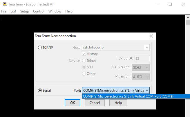
Here, we will use Tera Term. (If you don’t have it, please search for it on the Internet and download it.)
Start Tera Term, select Serial(E), and select the COM port that contains the STLink Virtual Com Port in Port(R): and click OK button.
In our environment, COM9 was assigned to the Virtual Com Port.
The ST system has created a virtual COM port environment, so let’s use it.
Next, go to Settings – Serial Port in the menu and set the communication parameters as follows, then click the OK button.
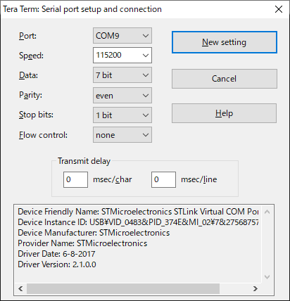
(Note: As I told you in my previous article, to use parity, the data length on the microcontroller side should be set to 8 and on the PC side to 7.
One more thing: Check the Local Echo checkbox in the Settings – Terminal screen.
Now, when you press a key, the character will be sent and displayed on the screen.
Connect the microcontroller board to the PC with a USB cable.
Coding
Code main.c as follows.
/* USER CODE BEGIN WHILE */ (1)
while (1)
{
  TransmitData();
  HAL_Delay(3000);
  /* USER CODE END WHILE */ /* USER CODE BEGIN 3

  /* USER CODE BEGIN 3 */ /* USER CODE END WHILE
}
/* USER CODE END 3 */ }
.
void TransmitData(void);

#define _CR 0x0d

void TransmitData(void)
{
  uint8_t buffer[] = {
    '#', 'a', 'b', 'c', 'd', 'e', _CR
  };

  for (int i = 0; i < sizeof(buffer); i++)
  {
    LL_USART_TransmitData9(USART2, (uint16_t)buffer[i]);
    while (!LL_USART_IsActiveFlag_TXE(USART2))
    {
      ;
    }
  }
}
When you are done coding, please build the program and make sure there are no errors.
Program Summary
If parity is included, the
LL_USART_TransmitData9() is used to transmit one byte of data.
(LL_USART_TransmitData8() in case of no parity)
This function starts the transmission by setting the data in the DR of USART.
Since data cannot be sent continuously, set the data when it is ready to be sent.
That's the while (!LL_USART_IsActiveFlag_TXE(USART2)) part.
TXE probably stands for Tx DR Empty, and the function returns 1 when the DR is empty.
To wait while it's not empty, we add ! to wait while it is not empty.
buffer The _CR (0x0d) at the end is a newline CR code.
Tera Term will accept this and return a new line.
Execute the program
First, double-click the line number of the while(1) line in main.c to put a breakpoint and run the program.
When the program is stopped at the breakpoint, the USART is already set.
Select Window - Show View - SFRs.
SFRs is Special Function Register, which stands for Register for Peripheral.
> Click on the > of USART2 to V and expand it to see the value of the register.
CR1 : 0x240c
CR2 : 0x0
CR3 : 0x0
So, we have the settings as we expected.
Now let's run the program.
Select "Run - Resume".
If you see the string #abcde every 3 seconds on your PC's Tera Term, you have succeeded.
Change the parity
Try to change the parity to 8bit in the Tera Term setup.
It is confirmed that the characters are garbled. This means that the data is sent in 7-bit format.
About polling transmission
Although polling transmission is easy to program, it has a disadvantage that it occupies the program from the beginning to the end of the transmission.
In the next article, we will look at sending using interrupts, which is more efficient.
That's all for now, thanks for your patience.


