
Hello everyone.
In this article, we will try to send LL UART communication using DMA.
What is LL? If you are wondering what LL is, please refer to the article HAL and LL.
The following is the development environment at the time of posting.
PC: Windows 10 OS
IDE: STM32CubeIDE Version1.5.0
Configurator: STM32CubeMX Version6.1.0
Board: STM32Nucleo-F401RE
What is DMA?
DMA stands for Direct Memory Access.
Normally, data is read from the peripheral (peripheral I/O) into memory via the CPU, and data is written from memory to the peripheral via the CPU.
With DMA, you can literally access memory directly, so there is no need to go through the CPU, and that time can be used for other processing.
In the last two articles, I wrote about interrupts and polling transmission.
DMA > interrupt > polling, in that order, is probably the most efficient use of the CPU.
Create a project
Start the IDE, select File- New – STM32 Project, when the Target Selection window comes up, select the Board Selector tab, select NUCLEO-F401RE from the Boards List and press Next. Click the Next button.
Enter F401UartLLTxDMA as the Project Name and press the Finish button.
When it asks “Initialize all peripherals with their default Mode ? Press Yes.
Preparing to use the UART with LL
Select the Project Manager tab and change the USART in Advanced Settings from HAL (default) to LL. (Use the combo box to select)
Click on the HAL section to display a list of combo boxes, and select LL.
Select Project – Build All.
It will ask “Do you want Generate Code ? Check the Remember my decision checkbox and press OK.
This action can be associated with C/C++ perspective.
This action can be associated with C/C++ perspective.
Modify UART parameters
Double-click F401UartLL.ioc from Project Explorer to open the GUI window.
Select Pinout & Configuration – Connectivity – USART2.
For Mode, Asynchronus is selected and ready to use. (Disable if you don’t want to use it.)
We will use parity again.
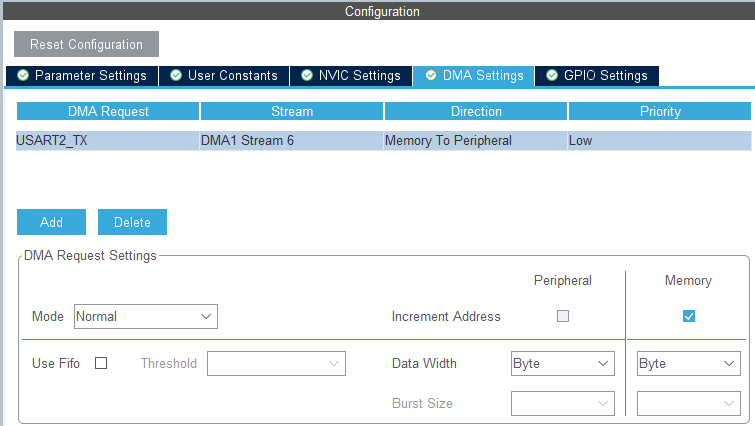
In the Configuration – Parameter Settings section, make the following settings.
(The only change from the default is to change Parity from None to Even)
Baud Rate : 115200
Word Length : 8bits
Parity : Even
Stop Bits : 1
Configure interrupt settings
Check the Enabled checkbox for USART2 global interrupt in Configuration – NVIC Settings.
Configure DMA settings
In Configuration – DMA Settings, press the Add button and select USART2_TX from the Select combo box.
Now let’s build it once to check the code.
Select Project – Build All.
STM32 DMA
In order to use LL and DMA in the future, we need to understand the registers of the peripherals.
To do so, please download the reference manual RM0368 for the microcontroller used in this board from here. We will use DMA to run the UART.
This time, we will use DMA to run UART, so please read the DMA section in section 9 and the USART section in section 19 carefully.
We have already explained about UART in detail in the last two articles, so we will explain about DMA here as much as we can.
The block diagram of DMA is shown below.
There are two DMA peripherals, 1 and 2, and several channels and streams.
Which one should I choose to use? I was wondering…

This figure below will help you solve the problem.
(In the reference manual, there is another unused DMA2 diagram below this one, so make sure you read through that one as well.)

It seems that each peripheral has its own combination of streams and channels that can be used.
In the case of USART2, the table is as follows.
Since this is a transmission, we will use 1 for the DMA peripheral, 6 for the stream, and 4 for the channel.
| DMA peripheral | stream | channel | |
|---|---|---|---|
| USART2 TX | DMA1 | 6 | 4 |
| USART2 RX | DMA1 | 5 | 4 |
Stream means “flow,” and you can think of it as a communication path.
DMA registers explained
Setting registers DMA_SxCR (x=0-7)
First, let’s look at the configuration registers.
The Sx part is the stream number. As explained earlier, we will be setting it to S6.
I will explain this based on what I read in the reference manual.
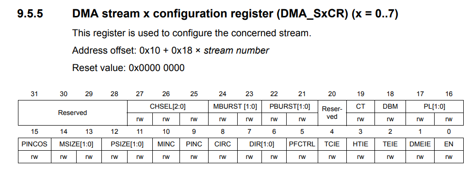
Bits 27, 26, 25 : CHSEL Channel selection
As explained above, 4
Bit 24,23 : MBURST Memory Burst Transfer Setting
0 for single transfer
Bit 22,21 : PBURST Peripheral Burst Transfer
0 for single transfer
Bit 19 : CT Current target
0 since single buffer is used
Current target memory is memory 0 (addressed by DMA_SxM0AR pointer)
Bit 18 : DBM Double buffer mode
0 since a single buffer is used.
Bit 17, 16 : PL Priority level
Low 0
Bit 15 : PINCOS Peripheral Increment Offset Size
0 because it is not used.
(When PINC = 0, this bit has no meaning.)
Bit 14,13 : MSIZE Memory data size
Byte 0
Bit 12,11 : PSIZE Peripheral data size
Byte 0
Bit 10 : MINC Memory Increment Mode
1 as it increments
Bit 9 : PINC Peripheral Increment Mode
0 because it does not increment
Bit 8 : CIRC Circular mode
Invalid 0
Bit 7, 6 : DIR Data transfer direction
Memory to peripheral 1
Bit 5 : PFCTRL Peripheral flow controller
DMA is flow controller 0
Bit 4 : TCIE Transmit Complete Interrupt Enable
Enable 1
Bit 3 : HTIE Enable 1/2 transfer interrupt
Not used, so 0
Bit 2 : TEIE Enable transfer error interrupt
0 since it is not used.
Bit 1 : DMEIE Enable direct mode error interrupt
Not used, 0
Bit 0 : Enable stream
0 when setting, 1 when sending
The value of DMA1_S6CR should be 0x08000450 when the initial settings are completed.
Data Register DMA_SxNDTR (x=0-7)

Here we write the size of the array buffer, sizeof(buffer), which is the number of bytes to send.
The value written here will be decremented each time it is sent, so it must be written each time it is sent.
Peripheral address register
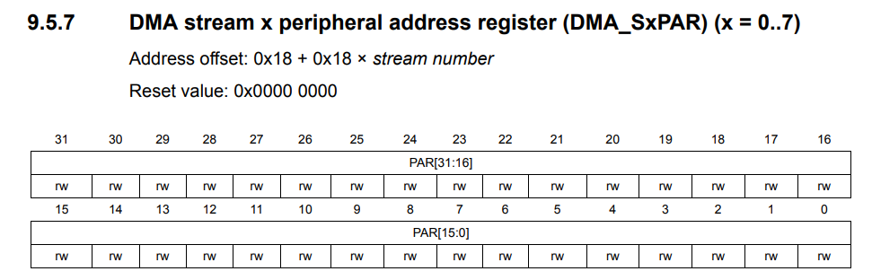
Specify the DR for USART2 here.
Memory 0 Address Register

This is where the memory address of the DMA transfer source is specified.
The memory 1 address register after this is omitted since it is not used in single buffer mode.
The FiFo control register is also omitted since it is not used.
Coding
main.c
The initialization code related to DMA is also generated within MX_USART2_UART_Init(), but the last two lines need to be added.
It will be easier to understand if you step through and check what each function of initialization is doing.
You can check the value of each register from Window – Show View – SFRs – DMA1.
static void MX_USART2_UART_Init(void)
{

  /* USER CODE BEGIN USART2_Init 0 */ /* USER CODE END USART2_Init 0

  /* USER CODE END USART2_Init 0 */

  LL_USART_InitTypeDef USART_InitStruct = {0}

  LL_GPIO_InitTypeDef GPIO_InitStruct = {0};

  /* Peripheral clock enable */ LL_APB1_GRP
  LL_APB1_GRP1_EnableClock(LL_APB1_GRP1_PERIPH_USART2);

  LL_AHB1_GRP1_EnableClock(LL_AHB1_GRP1_PERIPH_GPIOA);
  /**USART2 GPIO Configuration
  PA2 ------> USART2_TX
  PA3 ------> USART2_RX
  */ GPIO_InitStruct.
  GPIO_InitStruct.Pin = LL_GPIO_PIN_2|LL_GPIO_PIN_3;
  GPIO_InitStruct.Mode = LL_GPIO_MODE_ALTERNATE;
  GPIO_InitStruct.Speed = LL_GPIO_SPEED_FREQ_LOW;
  GPIO_InitStruct.OutputType = LL_GPIO_OUTPUT_PUSHPULL;
  GPIO_InitStruct.Pull = LL_GPIO_PULL_NO;
  GPIO_InitStruct.Alternate = LL_GPIO_AF_7;
  LL_GPIO_Init(GPIOA, &GPIO_InitStruct);

  /* USART2 DMA Init */ /* USART2_TX Init

  /* USART2_TX Init */
  LL_DMA_SetChannelSelection(DMA1, LL_DMA_STREAM_6, LL_DMA_CHANNEL_4);

  LL_DMA_SetDataTransferDirection(DMA1, LL_DMA_STREAM_6, LL_DMA_DIRECTION_MEMORY_TO_PERIPH);

  LL_DMA_SetStreamPriorityLevel(DMA1, LL_DMA_STREAM_6, LL_DMA_PRIORITY_LOW);

  LL_DMA_SetMode(DMA1, LL_DMA_STREAM_6, LL_DMA_MODE_NORMAL);

  LL_DMA_SetPeriphIncMode(DMA1, LL_DMA_STREAM_6, LL_DMA_PERIPH_NOINCREMENT);

  LL_DMA_SetMemoryIncMode(DMA1, LL_DMA_STREAM_6, LL_DMA_MEMORY_INCREMENT);

  LL_DMA_SetPeriphSize(DMA1, LL_DMA_STREAM_6, LL_DMA_PDATAALIGN_BYTE);

  LL_DMA_SetMemorySize(DMA1, LL_DMA_STREAM_6, LL_DMA_MDATAALIGN_BYTE);

  LL_DMA_DisableFifoMode(DMA1, LL_DMA_STREAM_6);

  /* USART2 interrupt Init */
  NVIC_SetPriority(USART2_IRQn, NVIC_EncodePriority(NVIC_GetPriorityGrouping(),0, 0));
  NVIC_EnableIRQ(USART2_IRQn);

  /* USER CODE BEGIN USART2_Init 1 */

  /* USER CODE END USART2_Init 1 */
  USART_InitStruct.BaudRate = 115200;
  USART_InitStruct.DataWidth = LL_USART_DATAWIDTH_8B;
  USART_InitStruct.StopBits = LL_USART_STOPBITS_1;
  USART_InitStruct.Parity = LL_USART_PARITY_EVEN;
  USART_InitStruct.TransferDirection = LL_USART_DIRECTION_TX_RX;
  USART_InitStruct.HardwareFlowControl = LL_USART_HWCONTROL_NONE;
  USART_InitStruct.OverSampling = LL_USART_OVERSAMPLING_16;
  LL_USART_Init(USART2, &USART_InitStruct);
  LL_USART_ConfigAsyncMode(USART2);
  LL_USART_Enable(USART2);
  /* USER CODE BEGIN USART2_Init 2 */

  // Here's the code I added myself.
  // No need to do it every time, so I wrote it here.

  // Transfer source, destination, direction
  LL_DMA_ConfigAddresses(DMA1, LL_DMA_STREAM_6, (uint32_t)&buffer, LL_USART_DMA_GetRegAddr(USART2), LL_DMA_DIRECTION_MEMORY_TO_PERIPH);

  // Enable transmit completion interrupt.
  LL_DMA_EnableIT_TC(DMA1, LL_DMA_STREAM_6);

  /* USER CODE END USART2_Init 2 */ (DMA1, LL_DMA_STREAM_6)

}
Write the function DMA_TransmitData() to send data around the front of the main() function.
/* USER CODE BEGIN 0 */
#define _CR 0x0d
#define _LF 0x0a

uint8_t buffer[] =
{
	'#', 'a', 'b', 'c', 'd', 'e', _CR, _LF
};

void DMA_TransmitData();

void DMA_TransmitData()
{

  LL_DMA_DisableStream(DMA1, LL_DMA_STREAM_6);

  LL_DMA_SetDataLength(DMA1, LL_DMA_STREAM_6, sizeof(buffer));

  LL_DMA_EnableStream(DMA1, LL_DMA_STREAM_6);

  LL_USART_EnableDMAReq_TX(USART2);
}

/* USER CODE END 0 */

/**
  * @brief The application entry point.
  * @retval int
  */ int main(void)
int main(void)
Inside the while() loop
while (1)
{
  DMA_TransmitData();
  HAL_Delay(1000);
  /* USER CODE END WHILE */
  /* USER CODE BEGIN 3 */ /* USER CODE END WHILE
}
stm32f4xx_it.c
DMA1_Stream6_IRQHandler() is an interrupt handler for DMA1 stream 6.
It adds a process to clear the transmit completion flag if it is present.
If the flag is not cleared, the next transmission will not be performed.
void DMA1_Stream6_IRQHandler(void)
{
  /* USER CODE BEGIN DMA1_Stream6_IRQn 0 */
  if( LL_DMA_IsActiveFlag_TC6(DMA1) == 1){
    LL_DMA_ClearFlag_TC6(DMA1);
  }
  /* USER CODE END DMA1_Stream6_IRQn 0 */

  /* USER CODE BEGIN DMA1_Stream6_IRQn 1 */ /* USER CODE

  /* USER CODE END DMA1_Stream6_IRQn 1 */ /* USER CODE
}
Tera Term Setup
The image is omitted because it has been shown many times.
Set up in the following way.
COM port : Select Serial in New Connection and select the STLink Virtual COM port.
From Settings – Serial Port
Speed : 115200
Data : 7bit
Parity : even
Stop bit : 1bit
Flow control : none
Check the Local Echo checkbox in the terminal settings.
Program overview
The configurator did most of the initial configuration for DMA, which was helpful.
About the two lines I added
First
LL_DMA_ConfigAddresses(DMA1, LL_DMA_STREAM_6, (uint32_t)&buffer, LL_USART_DMA_GetRegAddr(USART2), LL_DMA_DIRECTION_MEMORY_TO_PERIPH);
to set the respective addresses and directions of the memory and peripherals.
The interrupt settings needed to be done separately, so
LL_DMA_EnableIT_TC(DMA1, LL_DMA_STREAM_6);
to enable the transmission completion interrupt.
In DMA_TransmitData()
The number of bytes to be transmitted is set each time.
To set it, the stream must be disabled.
After that, transmission starts by requesting it with LL_USART_EnableDMAReq_TX().
Build and run
Build and make sure there are no errors.
Setup Tera Term on the computer side and run the program.
If #abcde is displayed every 1 second, the program is successful.
How did you like it?
Did the UART transmission using DMA work well?
Thank you for your time.


