
In this article, we will try to perform serial communication by polling with STM32 microcontroller.
The following is the development environment at the time of submission.
PC: Windows 10 OS
IDE: STM32CubeIDE Version 1.1.0
Configurator: STM32CubeMX Version5.4.0
Board: STM32Nucleo-F401RE
Serial communication is a relatively easy way to communicate, so if you haven’t used it before, this is a good time to give it a try.
Before that, I’d like to talk a little bit about deleting IDE projects.
About deleting projects
We are going to create many different projects.
It would be easier to understand if we separate the projects by function.
It is possible to manage multiple projects in the IDE, but it can be annoying.
For example, if you select “Build All”, it will build all the projects visible in the IDE, which takes a lot of time.
(If you select Build Project while a project is selected, only that project will be built.
It is also confusing to know which project the open file belongs to.
This is why it is best to keep only one project visible in the IDE to avoid problems.
There is a way to delete a project from the IDE but keep the actual project file on the disk.
(It would be a shame to delete the project from the disk as well, since you have already created it.
In the IDE’s Project Explorer, right-click on the project name (in this case, F401, which was created last time) and select Delete from the menu that appears.
Then the following window will appear.
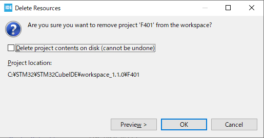
If you check the checkbox here, it will actually delete the project file from the disk.
And please note that you will not be able to undo it.
If you press the OK button without checking the box, the file will not be deleted and will not be visible in the IDE.
It is useful to have only one project visible in the IDE in this way.
(Note: There is a risk of accidentally deleting project files with this method, so it is recommended that you make a backup of your project files before doing this.
Importing a Deleted Project
Projects whose files have not been deleted from disk can be imported to appear in the IDE.
Select File – Import.
Select General – Existing Projects into Workspace and press the Next button.
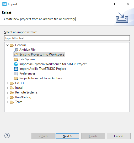
With the Select root directory selected, click the Browse… button on the right to select the project to import. Select the project you want to import and click the Finish button.
Now you can see the invisible project in the IDE.
This time we will create a new project, so please delete it again to make sure that the F401 project is not visible in the IDE.
Creating a project for serial communication
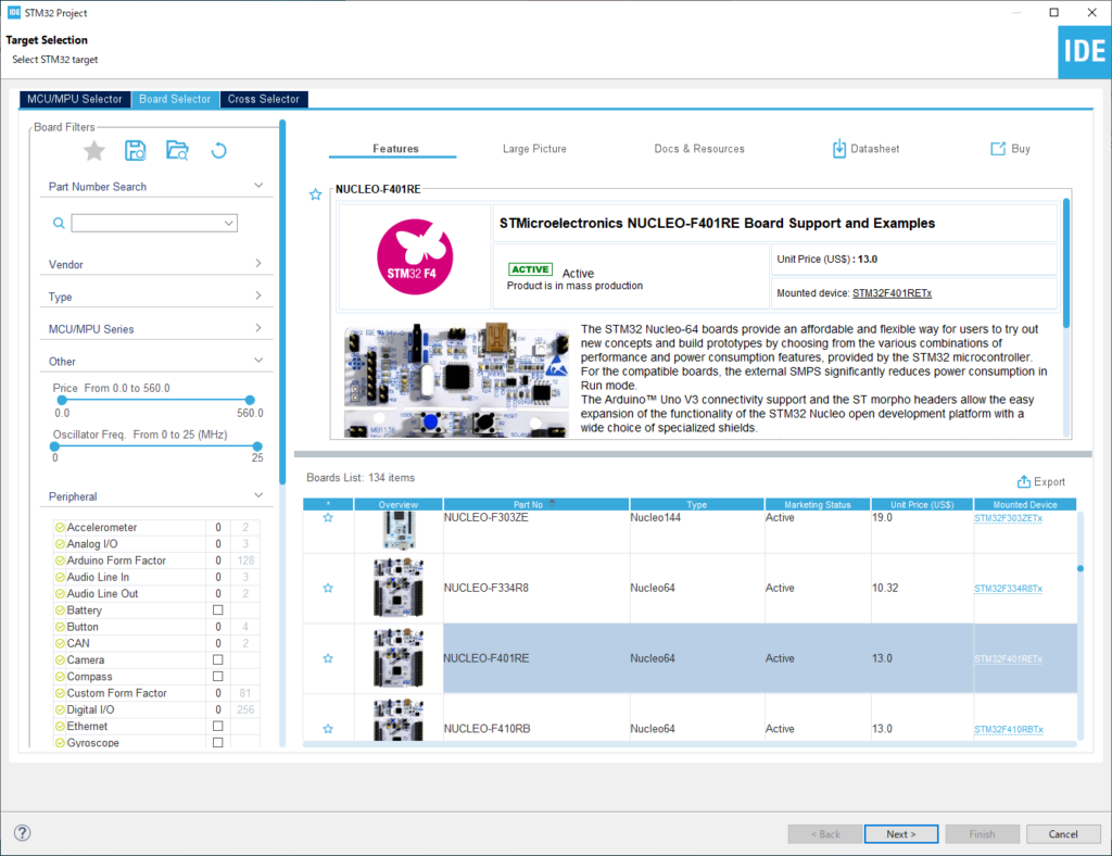
Select File – New – STM32 Project from the menu.
In the Boart Selector, click on NUCLEO-F401RE from the Boart List to select it and press the Next button.
In the Project Name field, enter the project name (for example, F401UartPolling in this case) and press the Finish button.
Press the Yes button.
Double-click F401UartPolling – Core – Src – main.c in the Project Explorer to open the file.
In the main() function, there is a function called MX_USART2_UART_Init().
This function is generated by initialization in default mode.
The initialization assigns PA2 to TX (transmit) of USART2 and PA3 to RX (receive) of USART2.
Looking at the schematic, you can see that these pins are connected to the microcontroller for the debugger.
When the microcontroller is connected to the PC with a USB cable, it is recognized as a virtual COM port by the PC.
This creates an environment for serial communication.
In general
Microcontroller – RS232C driver IC <---RS232C cross cable---> RS232C driver IC – Microcontroller
But with STMicro boards, you only need to connect them with a USB cable, which is convenient for testing serial communication.
With the board selected and the peripheral functions initialized in default mode, the USART functions are ready to be used.
Preparing the PC side
On the PC side, we need to prepare an application that can send and receive data.
In this example, I will use Tera Term.
Tera Term is a terminal software for Windows.
Tera Term is a free software.
You can search for it on the Internet or download it from this site.
It can be used to control devices connected to the serial port of a PC, or to control another computer on the network via Telnet or ssh.
In Japan, Tera Term is often used, so I use it as well.
If you have a familiar terminal software, you can use it as well.
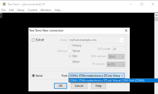
Start Tera Term, select Serial(E), select Port(R):, select the COM port that contains STLink Virtual Com Port, and click OK button.
In our environment, COM3 was assigned to the Virtual Com Port.
The ST system has created a virtual COM port environment, so let’s use it.
Next, go to Settings – Serial Port in the menu and set the communication parameters as shown below and press the OK button.
These should match the values set in MX_USART2_UART_Init().

One more thing: Check the Local Echo checkbox in the Settings – Terminal screen.
Now when you press a key, it will send the character to the screen.
Make sure to connect the microcontroller board to the PC with a USB cable.
Let’s try coding
Now let’s implement the communication part of the program.
As mentioned in the project name, we will be using polling as the communication method.
Polling is a method that does not use interrupts, and here we will periodically check for incoming data.
First, we will define variables at the beginning of main().
int main(void)
{
  /* USER CODE BEGIN 1 */
  uint8_t buffer[256];
  HAL_StatusTypeDef s;
  /* USER CODE END 1 */
Next, please describe the while() loop part as follows.
  /* USER CODE BEGIN WHILE */
  While (1)
  {
    /* USER CODE END WHILE */
    /* USER CODE BEGIN 3 */
    s = HAL_UART_Receive(&huart2, buffer, 1, 3000);
    if (s == HAL_TIMEOUT)
    {
      HAL_UART_Transmit(&huart2, "UART Timeout.\r\n", 15, 10);
    }
    else if (s == HAL_OK)
    {
      HAL_UART_Transmit(&huart2, buffer, 1, 10);
    }
  }
  /* USER CODE END 3 */
When you are done coding, build the program and make sure there are no errors.
Program Overview
Press any key on the PC side.
s = HAL_UART_Receive(&huart2, buffer, 1, 3000); to start receiving.
For more details about HAL_UART functions, see the HAL manual.
The HAL manual for STM32F4 series is available at here.
HAL_UART_Receive()
First argument: Pointer to the UART structure.
huart2 is a variable of the structure used in MX_USART2_UART_Init().
Second argument: Pointer to a buffer of type uint8_t.
Third argument: Specifies the size of the received data. Since this is an exercise, it is set to 1 byte.
4th argument: Specifies the timeout value. The unit is msec.
A value of type HAL_StatusTypeDef is returned.
It will return from the function when it receives 1 byte of data or times out.
Here, the timeout value is set to 3 seconds.
When it times out, it sends back “UART Timeout.\r\n”.
If something is received, the received value is sent directly by HAL_UART_Transmit().
HAL_UART_Transmit()
First argument: Pointer to a UART structure.
Second argument: Pointer to a buffer of type uint8_t.
3rd argument: Specifies the size of the transmitted data.
Fourth argument: Specifies the timeout value. The unit is msec.
Returns a value of type HAL_StatusTypeDef.
Estimating the communication time
Now let’s estimate how long the communication time will take.
The UART communication method is known as the synchronous method, and the format is as shown in the following figure.
S at the beginning : Start bit
D0-7 : Data bits (in the case of 7 bits, it will be D0-6)
P : Parity bit
ST : Stop bit
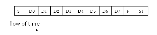
Since the data length is set to 8 bits, including parity, one byte of data will consist of 11 bits, but since there is no parity this time, it will be 10 bits.
The data to be sent in case of timeout is 15 bytes.
The unit of communication speed is bps, which stands for bits per second. This is the number of bits sent per second.
So the time per bit is the reciprocal of 1/115200 [sec].
The communication time to send 15 bytes of data is (1/115200) x 10 x 15 = about 1.3[msec].
The timeout value of 10 for HAL_UART_Transmit() when transmitting is large enough compared to 1.3msec, so it is probably a reasonable value.
If the timeout value is smaller than the communication time, all the data cannot be sent, so it is a good idea to estimate the communication time when using HAL_UART_Transmit().
Try to run the program
Now, let’s try to run the program with Run – Resume.
If it works as explained in the overview, it is a success.
According to the manual, HAL_UART_Transmit() and HAL_UART_Receive() are written in the Polling mode IO operation section.
So, they are functions used in polling mode.
Polling is a way to occasionally check to see if a signal has been received, and does not use interrupts.
The point to note is that the function will not return until the process is complete.
This mode of not coming back until the process is complete is called blocking mode.
In the next article, we will try serial communication in non-blocking mode using interrupts.


